Enter for the full results page · Esc to close

4 to 18 CWDM channels on one fiber pair, 1U rack. Built to your channel plan and swept channel by channel before it ships.
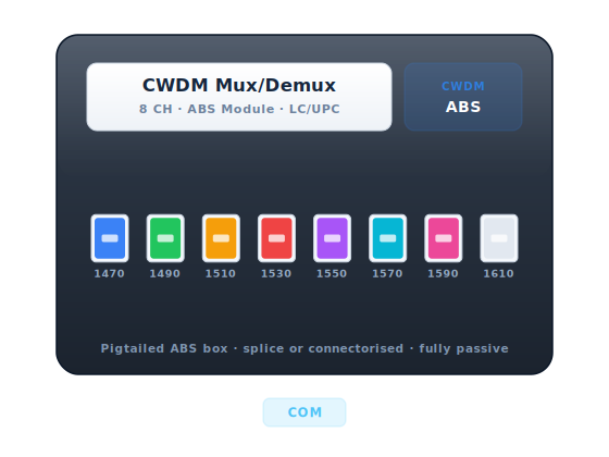
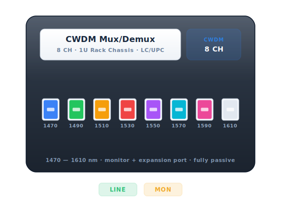
A passive CWDM multiplexer in a 1U 19-inch chassis. It puts up to eighteen 20 nm-spaced wavelengths onto a single fiber pair and separates them again at the far end — multiplying the capacity of fiber you already own, with no power, no electronics and nothing to fail.
The optics are thin-film filter (TFF) based: dielectric filter stacks deposited on glass, aligned and epoxy-free bonded, then swept channel by channel before the unit is closed. There is nothing powered inside, so there is nothing to fail, no heat to remove and no software to patch — the module simply keeps working for the life of the plant.
Every unit is built to your channel plan and supplied with its measured sweep data: per-channel insertion loss, adjacent and non-adjacent isolation, return loss and PDL. Package, connector type, polish and pigtail length are all build options, and the filter platform is qualified to Telcordia GR-1221-CORE.
| Grid | ITU-T G.694.2, 20 nm spacing |
|---|---|
| Wavelength range | 1271 – 1611 nm |
| Channels | 8 |
| Insertion Loss | ≤ 2.8 dB |
| Channel Isolation | ≥ 40 dB adjacent / ≥ 45 dB non-adjacent |
| Return Loss | ≥ 45 dB |
| PDL | ≤ 0.2 dB |
| Directivity | ≥ 50 dB |
| Fiber | Dual fiber — separate mux and demux |
| Package | 1U 19-inch rack-mount chassis |
|---|---|
| Connector | LC/UPC |
| Monitor Port | 1% tap fitted |
| Expansion Port | Available for cascading |
| Operating Temp | -5 °C to +70 °C |
| Compliance | Telcordia GR-1209-CORE / GR-1221-CORE, RoHS |
| Optical Test | 100% — every channel swept for insertion loss, isolation and return loss |
|---|---|
| Test Report | Per-unit measured data supplied with the shipment |
| Traceability | Serialized; serial links to the sweep record and production batch |
| Environmental Qualification | Telcordia GR-1221-CORE reliability testing on the filter platform |
| Customisation | Channel plan, port count, package, connector and pigtail length built to order |
| Lead Time | Stock configurations 3–5 days; custom channel plans 7–10 days |
| Warranty | 3 years |
| Part Number | Configuration | Channels | Availability |
|---|---|---|---|
| FOT-WDM-CWDM-RACK | Standard configuration | 8 | Build to order |
| FOT-WDM-CWDM-RACK-4CH | Channels: 4 CH | 4 | Build to order |
| FOT-WDM-CWDM-RACK-16CH | Channels: 16 CH | 16 | Build to order |
| FOT-WDM-CWDM-RACK-18CH | Channels: 18 CH | 18 | Build to order |
| FOT-WDM-CWDM-RACK-SF | Fiber: Single fiber (BiDi) | 8 | Build to order |
Part numbers are indicative. Send us the channel plan, package and connector and we confirm the exact build code on the quotation.
Insertion loss, isolation, return loss and PDL measured on every port of every unit.
Serial number links to the measured sweep record and the production batch.
Channel list, port count, package, connector polish and pigtail length are all build options.
Dust-capped and individually bagged with the test report, packed in export cartons.
Multiply the capacity of leased or owned dark fibre without trenching a single extra strand.
Aggregate access rings and overlay new services onto fibre that is already lit.
Colour the radio sites so one fibre pair serves a whole cluster of cells.
Join buildings, DR sites and storage replication over a single inter-site pair.
The CWDM grid gives eighteen 20 nm-spaced channels from 1271 to 1611 nm. In practice the six 1351–1451 nm channels sit in or near the water peak, so on older non-zero-water-peak fiber (G.652.B) many operators use only the eight 1471–1611 nm channels. On modern G.652.D fiber all eighteen are usable.
Yes — a mux at one end and a demux at the other, or more commonly an identical mux/demux unit at both ends so the link works in either direction. Order in pairs unless you are extending an existing site.
It taps 1% or 2% of the aggregate line signal so you can measure total launch power with a meter without breaking traffic. Very useful for commissioning and for proving a fault is outside your equipment.
Yes — that is most of what we ship. Send the wavelength or ITU channel list, the port count, the package and the connector type on your RFQ and we build to it. Custom plans add only a few days to lead time.
Take the insertion loss shown for your channel count and double it, because you need a unit at each end of the link. Then add roughly 0.3 dB per mated connector pair and 0.1 dB per splice, and keep 3 dB of margin for ageing and future repairs before you compare against the transceiver's link budget.
Yes. Every unit is swept channel by channel and the measured insertion loss, isolation and return loss are supplied with the shipment. Sample reports can be provided in advance for tender documentation.
Tell us the platform and the quantity. An engineer checks the part against your switch and software version before quoting — if it will not work, we say so.
Goes to our engineers and the quotation desk together. Replies come from sales@topnetsystem.com, usually within one working day.