Optical Communication Products · Shenzhen, China
Tel: +86 0755 23766314  ·  marketing@fotfiberoptic.com
Request a Quote

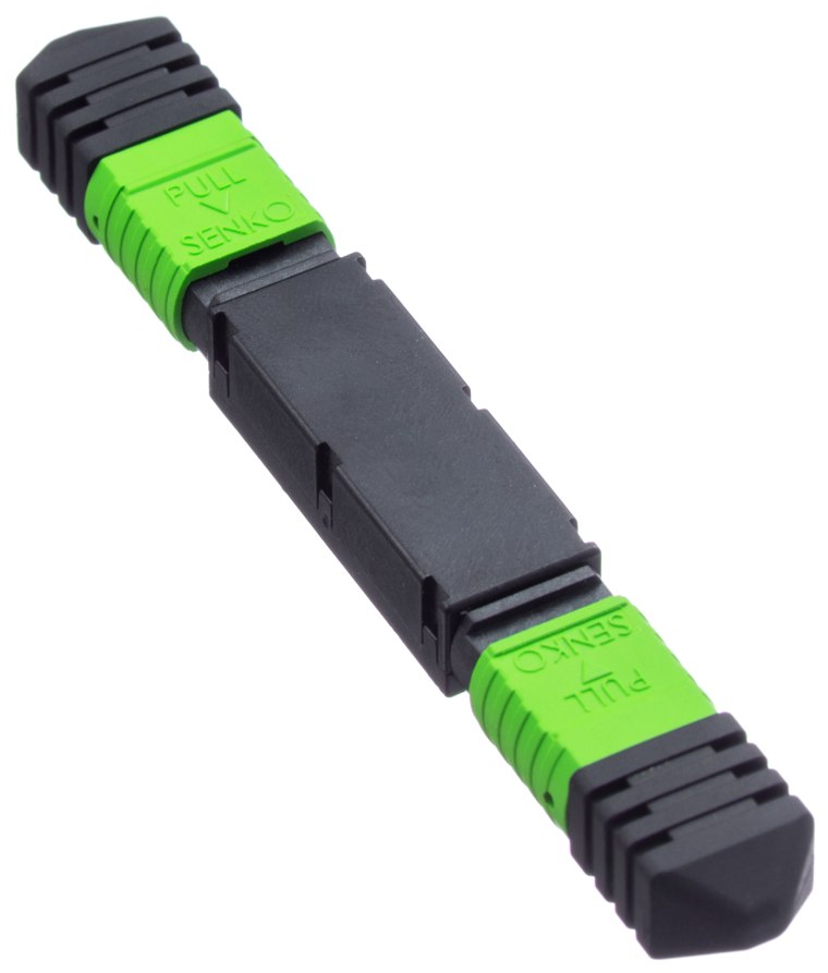
MPO/MTP Fixed Attenuator

SKU: FOT-MPO-ATT · Test & Maintenance

Add a calibrated 1–20 dB per fibre inside an MPO adapter.

12FFibre count
5 dBAttenuation
± 0.5 dBTolerance
PassiveMale-female inline
Attenuation
5 dB1 dB2 dB3 dB7 dB10 dB15 dB20 dB
Fibre count
12F8F16F24F
Fibre type
OS2 single-mode (G.652.D)OM4 multimodeOM3 multimode
Polish
APC (angled, 8°)UPC / PC (flat)
Format
Male-female inlineFemale-female build-out
Configured part numberFOT-MPO-ATT
Ships worldwide
Built to your configuration
3-year warranty
Product Overview

Sometimes the problem is too much light. A fixed MPO attenuator adds a calibrated, equal loss to every fibre in the connector, bringing receive power back inside the operating window on a short link that was never designed to be short.

Assemblies are built on US Conec MTP® ferrules and terminated in a controlled environment, then measured fibre by fibre. Interferometry checks the three geometry parameters that decide whether a multi-fibre ferrule mates properly — radius of curvature, apex offset and fibre height — and every end face is inspected and graded to IEC 61300-3-35 before the dust cap goes on.

Fibre count, fibre type, polish, polarity, gender, jacket rating, leg length and overall length are all build options rather than catalogue limits. Use the selector above to configure the exact assembly and the specification table will follow your choices; the measured test report ships with the cable.

Technical SpecificationsUpdates with your selection

Optical
Fiber Count12F
Attenuation5 dB
Attenuation Tolerance± 0.5 dB per fibre
Fiber TypeOS2 single-mode, G.652.D — Corning SMF-28 Ultra
Wavelength1310 / 1550 nm
Return Loss≥ 60 dB
Connector PolishAPC — 8° angled, green housing
Attenuation MethodDoped-fibre — flat across the band, no wavelength tilt
Mechanical & Environment
FormatMale-to-female inline, mates between connector and adapter
Uniformity≤ 0.5 dB spread between the fibres of one connector
Power Handling≤ 300 mW
Operating Temp-10 °C to +60 °C
ComplianceIEC 61754-7, Telcordia GR-910-CORE, RoHS
Jacket ColourYellow
Testing, Quality & Supply
Optical Test100% — every fibre measured for insertion loss and return loss before shipment
Ferrule GeometryInterferometer-verified: radius of curvature, apex offset and fibre height to IEC 61755-3
End-Face InspectionEvery ferrule inspected and graded to IEC 61300-3-35
Test ReportPer-fibre measured data supplied with the assembly, traceable to the serial number
Connector SourceUS Conec MTP® ferrules; genuine-brand or FOT MPO to your preference
CustomisationFibre count, type, polish, polarity, gender, jacket, leg length and overall length built to order
Lead TimeStock configurations 3–5 days; custom builds 7–10 days
Warranty3 years

Ordering Information

Part NumberConfigurationFibre countAvailability
FOT-MPO-ATTStandard configuration12FBuild to order
FOT-MPO-ATT-1DBAttenuation: 1 dB12FBuild to order
FOT-MPO-ATT-2DBAttenuation: 2 dB12FBuild to order
FOT-MPO-ATT-3DBAttenuation: 3 dB12FBuild to order
FOT-MPO-ATT-7DBAttenuation: 7 dB12FBuild to order
FOT-MPO-ATT-10DBAttenuation: 10 dB12FBuild to order
FOT-MPO-ATT-15DBAttenuation: 15 dB12FBuild to order
FOT-MPO-ATT-20DBAttenuation: 20 dB12FBuild to order
FOT-MPO-ATT-8FFibre count: 8F8FBuild to order

Part numbers are indicative. Send us the fibre count, type, polish, polarity, gender, jacket and length and we confirm the exact build code on the quotation.

Quality & What's in the Box

Measured Fibre by Fibre

Insertion loss and return loss recorded for every fibre, not sampled.

Geometry Verified

Interferometer data on ferrule radius, apex offset and fibre height.

Inspected & Graded

Every end face checked against IEC 61300-3-35 before packing.

Packaging

Dust-capped, coiled on a reel or in a bag with the test report and pulling sock.

Typical Applications

Data Centre Spine & Leaf

Parallel 40G/100G/400G/800G backbone between spine, leaf and top-of-rack panels.

AI / GPU Clusters

Rail-optimised accelerator fabrics where one switch port breaks out to several GPUs.

Structured Cabling

Pre-terminated backbone that installs in hours instead of days, with the loss budget known up front.

Test & Commissioning

Loopbacks, attenuators and inspection for proving ports before the link goes live.

Frequently Asked Questions

When do I actually need one?

When a long-reach optic is used on a short link. An ER or ZR-class module launching into 50 m of fibre will drive the far-end receiver above its overload threshold — the link either errors or does not come up at all. Add the difference between the launch power and the receiver's maximum, plus a couple of dB of margin, as fixed attenuation.

Is the attenuation the same on every fibre?

Within ± 0.5 dB, yes — that is the specified uniformity, and each unit is measured. It matters for parallel optics, because a lane that is 3 dB down relative to its neighbours will fail on its own while the aggregate power still looks fine.

How is the assembly labelled?

Both ends carry a printed label with the part number, fibre count, fibre type, polarity type and the serial number, and breakout legs are individually numbered. Tell us your own labelling convention on the RFQ and we print to it — it costs nothing and it saves an afternoon at installation.

Can I get free samples before ordering volume?

Yes. We supply qualification samples so you can measure the loss and check the fit in your own panels before committing. Per-order test reports are standard, and sample reports can be provided in advance for tender documentation.

Related MPO / MTP Products

Request a quote for this part

Tell us the platform and the quantity. An engineer checks the part against your switch and software version before quoting — if it will not work, we say so.

Goes to our engineers and the quotation desk together. Replies come from sales@topnetsystem.com, usually within one working day.