How to Choose a Fixed Optical Attenuator (and When You Need One)
Every optical receiver publishes two numbers: sensitivity (the least power it can decode) and overload (the most it can stand). Engineers obsess over the first and forget the second — then a short DWDM hop or a 10 m SR4 jumper delivers a signal so strong the receiver clips, and the "strong" link runs at 10-6 BER while every meter reading looks great. The cure costs less than the coffee consumed debugging it. This guide covers sizing, choosing and placing it correctly.
Receiver Overload: the Silent Link Killer
Photodiode front-ends are linear over a window — typically 20 dB or so. Above the overload point (often −5 to −8 dBm for long-reach SM optics), the amplifier chain saturates: eye diagrams flat-top, PAM4 levels smear together, and FEC burns its margin correcting errors that more power only worsens. Typical danger zones: 80 km-rated DWDM optics on a 5 km metro hop (+2 dBm arriving where −10 is ideal), EDFA outputs feeding short spurs, and analog CATV receivers where clipping appears directly as picture distortion.
How Overload Presents
- Errors that improve when you add loss — the definitive test: insert 5 dB; if BER drops, you were overloaded.
- A link that worked at 40 km failing when re-deployed at 2 km with the same optics.
- Pre-FEC BER rising as connectors are cleaned (cleaning removed loss the link accidentally relied on).
- Rx power alarms at the high threshold — the one alarm class nobody configures.
Sizing the dB Value (Worked Examples)
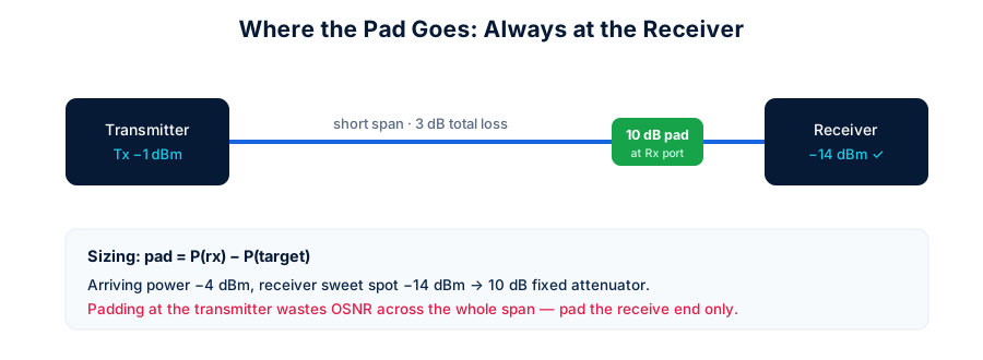
pad = Parriving − Ptarget, where target sits mid-window of the receiver spec. Three worked examples:
| Scenario | Arriving | Rx window | Target | Pad |
|---|---|---|---|---|
| DWDM ZR optic on 8 km metro hop | +1 dBm | −7 … −24 | −15 | 15 dB (round from 16) |
| GPON OLT bench test, 1 m cord | +3 dBm | −8 … −27 | −17 | 20 dB |
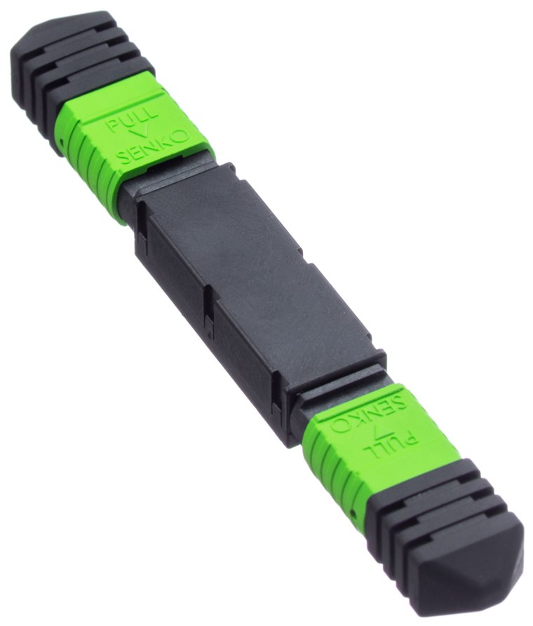
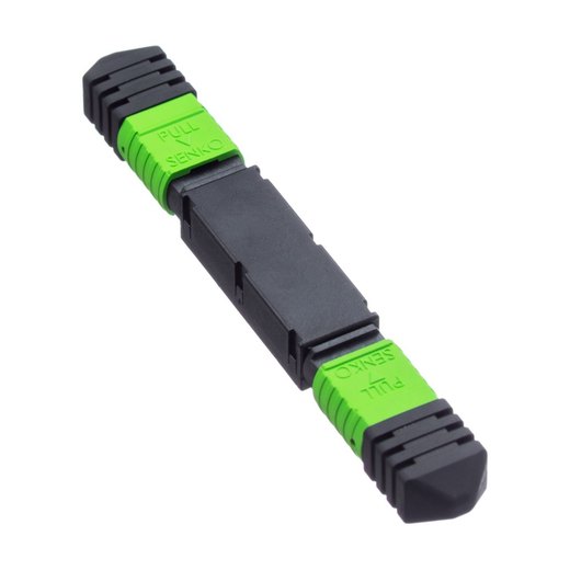
| 100G-SR4, 10 m OM4 | −1 dBm/lane | −3 … −10.3 | −7 | 5 dB (MPO pad — all lanes at once) |
Round to stocked values (1–30 dB in 1 dB steps; 3/5/10/15/20 ship same-day). Accuracy on FOT units: ±0.5 dB at ≤5 dB, ±10% above — tight enough that calculated placement lands mid-window without iteration.
Inside the Attenuator: Doped Fiber vs Air Gap
Quality fixed attenuators use a short section of metal-ion doped fiber that absorbs light in the glass itself. Absorption is spectrally flat (same dB at 1310 and 1550 nm), polarization-independent, and thermally stable from −40 to +80 °C. Cheap alternatives — air gaps, offset splices, bent fiber — attenuate by misdirecting light instead of absorbing it: they reflect (RL collapses to 30-something dB), drift with temperature, and change value with wavelength. If a datasheet doesn't say doped fiber, assume gap. Every FOT pad is doped-fiber, measured at both windows before shipping, with RL ≥50 dB (UPC) / ≥60 dB (APC) preserved through the pad.
Plug-Type vs Flange vs VOA vs In-Line
| Type | Form factor | Best at | Watch out |
|---|---|---|---|
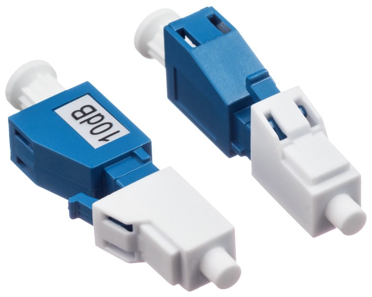
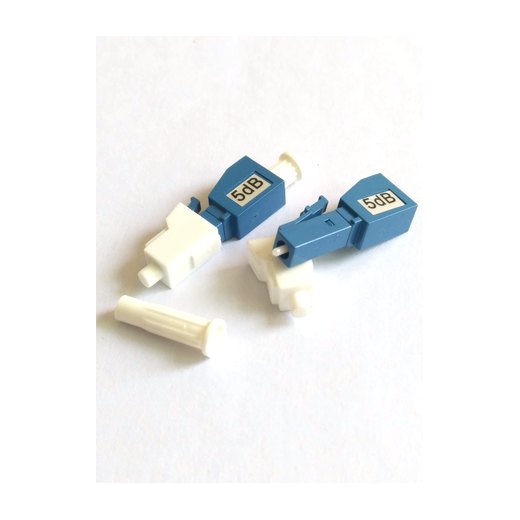
| Plug-type (male-female) | Inserts into an existing port; cord plugs into its rear | Equipment ports, panels — zero extra parts, the 90% answer | Match polish AND connector — LC/SC/FC/ST/MU/E2000 × UPC/APC all stocked |
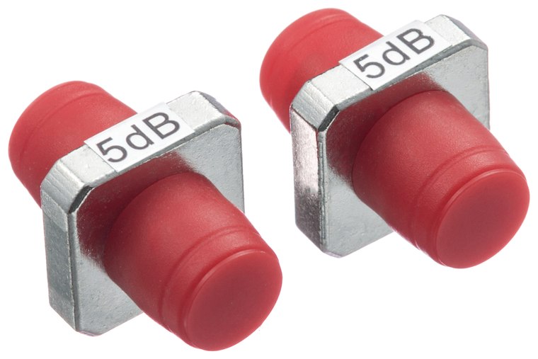
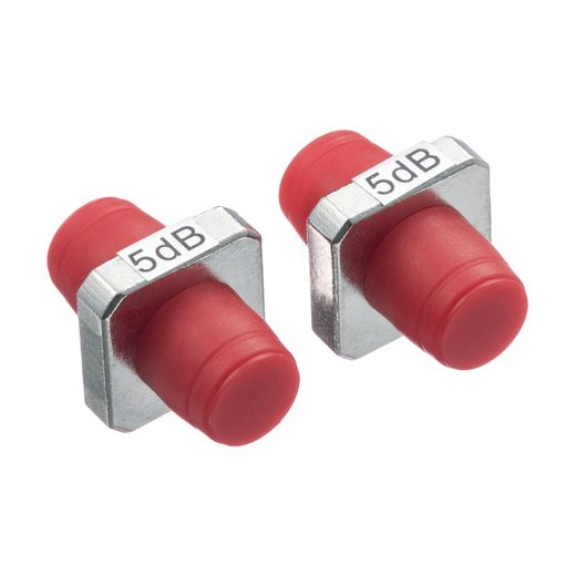
| Flange (LC / SC / FC) | Female-female; replaces an adapter | Joining two cords with attenuation mid-path; FC's threaded body shrugs off vibration | Adds one more mated pair to the loss budget |
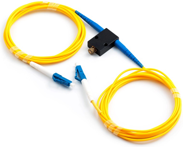
| Screw-adjust VOA | In-line 0–30 dB, jam-collar lock | Labs, commissioning, budgets that change | Set-and-lock; not a precision instrument at the bottom of its range |
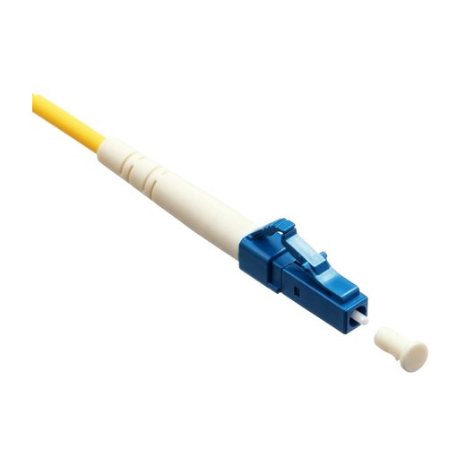
| In-line VOA (pigtailed) | Tuning block built into a jumper | Permanent installs needing occasional trim — EDFA balancing, OSNR tuning | Order correct connectors up front; it IS the patch cord |
Placement Rules
- Receive end, always. Padding at the transmitter drops power along the entire span — OSNR degrades, OTDR dynamic range shrinks, and mid-span taps starve. Padding at the receiver affects only the last centimeter.
- After the last amplifier, never before one — attenuating an EDFA's input raises its noise figure.
- Polish matching is absolute: UPC pad in UPC port, APC in APC (why cross-mating destroys ferrules).
- Label the value at the port. A hidden 10 dB pad is tomorrow's "mystery loss" ticket. We laser-mark values on the housing; add a flag label anyway.
Four Field Cases
- Metro DWDM turn-up: 40 ch mux → 6 km → demux; long-reach coherent optics arrive at +1 dBm. One 15 dB LC flange pad per channel port at the receive frame; pre-FEC BER drops four decades.
- GPON lab rack: OLT ports overload ONTs on 2 m test cords. 20 dB SC/APC plug-types emulate the real ODN loss — test results finally match field behavior.
- 100G-SR4 in-row: 8 m hop errors intermittently; per-lane Rx reads −0.8 dBm. A single MPO 12F 5 dB pad at the switch port pads all lanes uniformly — no per-fiber breakout needed.
- Burn-in bench: in-line VOAs on each DUT channel sweep sensitivity curves 0→30 dB without touching a connector.
Installation & Verification Checklist
- Read Rx power before (transceiver DDM or meter) — confirm overload is the actual problem.
- Inspect and clean both interfaces; a pad on a dirty port just relocates the fault.
- Insert pad at receive port → re-read DDM: arriving power should drop by the pad value ±0.5 dB. A bigger delta means a polish mismatch or contamination.
- Confirm post-FEC errors at zero over a soak (15 min minimum, a shift ideally), then label the port.
The FOT Attenuator Family
The complete series from one line: plug-type in six interfaces × both polishes (click options on the page — photos switch per version), flange in LC/SC/FC, screw VOAs in five interfaces, pigtailed in-line VOAs, and the hard-to-source MPO 12-fiber pad. Doped-fiber cores, dual-window test data, 1–30 dB.