MPO/MTP Polarity Explained: Type A, B and C Made Simple
MPO polarity is the most Googled topic in structured cabling for a simple reason: every mistake is invisible until power-on. Twelve connectors click perfectly, the certifier passes fiber continuity, and the link is still dark because lane 1's transmitter landed on lane 3's transmitter. This guide builds the mental model once, properly, so you never debug polarity by trial-and-error again.
Why Polarity Exists at All
Any optical link needs each transmit fiber to arrive at a receive port. Duplex LC solves it trivially — the A/B flip is molded into every adapter. An MPO ferrule carrying 12 or 16 fibers in a row has no such automatic flip: something in the channel must swap Tx→Rx, and the standards give you three places to do it — the trunk, the cassette, or the jumper. Polarity "types" are just labels for where the flip lives.
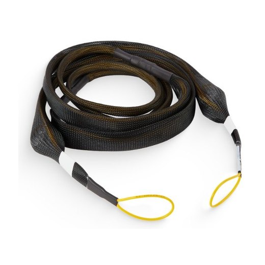
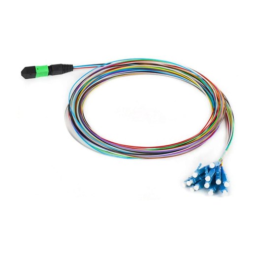
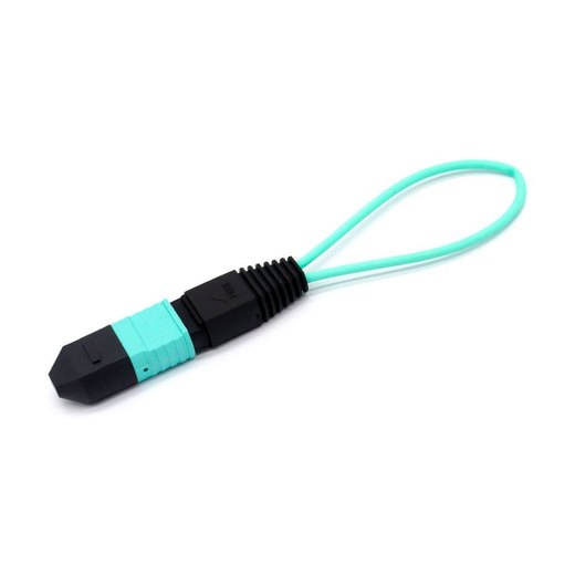
Connector Anatomy: Keys, Pins, Position 1
Three physical features control everything:
- The key — a raised tab on one side of the housing. Adapters mate connectors either key-up/key-down (most common) or key-up/key-up; this orientation is half of the polarity math.
- Guide pins — two steel pins on male connectors that enter the pin holes of female connectors, aligning the fiber rows to sub-micron accuracy.
- Position 1 (P1) — with the key up and the ferrule facing you, P1 is the leftmost fiber. Every FOT trunk prints a P1 marker so counts never start from the wrong end.
Types A, B and C — the Mappings
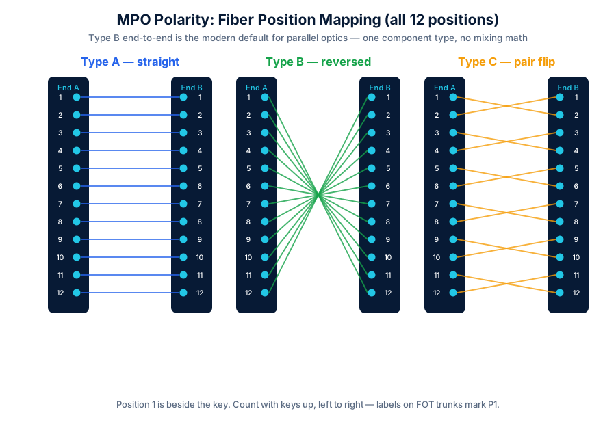
| Type | Mapping | Key orientation | Where the flip happens |
|---|---|---|---|
| A straight | 1→1, 2→2 … 12→12 | Key-up to key-down | Not in the trunk — a cassette or one A-to-B jumper must flip |
| B reversed | 1→12, 2→11 … 12→1 | Key-up to key-up | In every component — flips cancel in pairs, survive in odd counts |
| C pair-flip | 1→2, 2→1, 3→4 … | Key-up to key-down | Inside the trunk, per duplex pair — legacy duplex systems only |
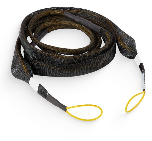
Type C dies with parallel optics: a SR4 lane group spans positions 1–4, and C's pairwise flip scrambles it. For 40/100/400/800G, the industry consolidated on Type B end-to-end — every trunk, every jumper identical, and an odd number of components in any path always yields exactly one net flip. One SKU to stock, no mixing math: this is why our trunk bundles ship Type B unless you order otherwise.
TIA Methods A/B/C: Whole-Channel Recipes
TIA-568 describes three connectivity methods (unfortunately reusing the letters) that combine trunks, cassettes and jumpers into a working duplex channel. Summarized:
| Method | Trunk | Cassettes | Jumpers | Verdict |
|---|---|---|---|---|
| A | Type A | Same both ends | Straight one end, crossed other end | Two jumper SKUs — the crossed one always goes missing |
| B | Type B | Same both ends | Standard duplex both ends | ✅ One SKU everywhere; scales to parallel natively |
| C | Type C | Same both ends | Standard duplex | Duplex-only; obsolete for lane-based optics |
Gender Rules That Prevent Broken Pins
Every MPO mating needs exactly one male (pinned) and one female (unpinned) side. The stable conventions:
- Transceivers are male. The jumper into any SR8/DR8 optic must be female on that end. No exceptions in current MSAs.
- Behind-the-adapter trunk ends are usually male, presenting pins to the female patch side through the bulkhead.
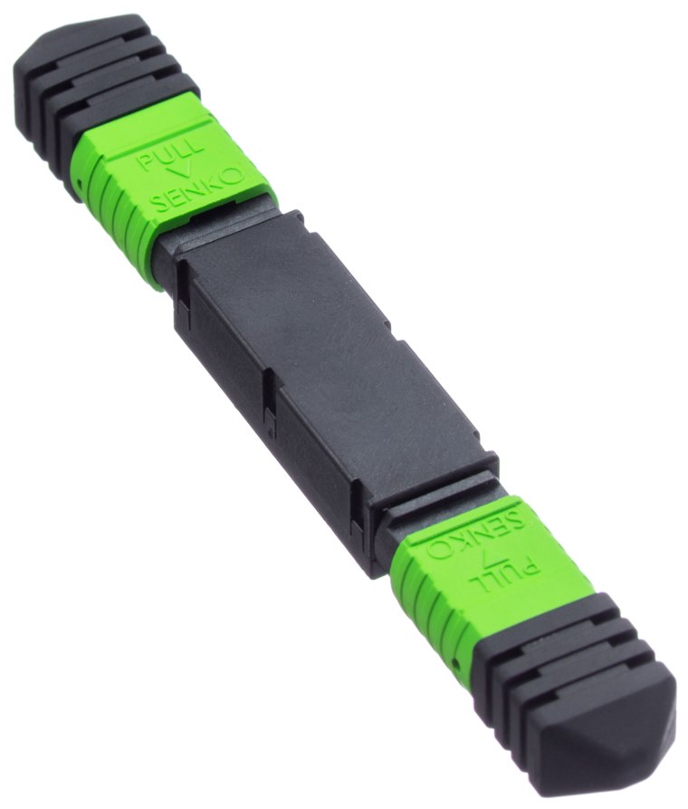
- Count pins before you push. Male-to-male bends guide pins (scrap both ferrules); female-to-female floats unaligned (huge, unstable loss). Both mistakes click home and feel fine.
Base-8, Base-12, Base-24 and 16-Fiber
MPO housings hold 12, 16, 24 or 32 fibers, and the grouping convention matters as much as the count. SR4-era optics use 8 of 12 fibers (positions 1-4 and 9-12) — "Base-8" trunks simply omit the four dark fibers and cost less. 400G/800G-SR8 moved to 16-fiber single-row (Base-16) connectors: one MPO16 carries all 8 lanes with none dark, the cleanest match for SR8 harnesses. Base-24 dual-row remains common for high-density LC fan-outs. Rule: match the base architecture to the optic family you'll run, not the biggest number available.
A Worked 400G Channel
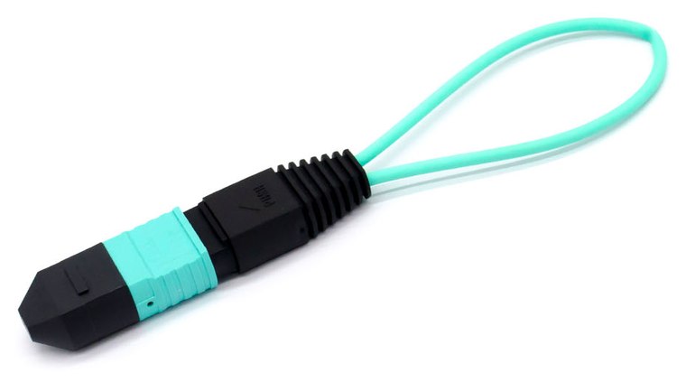
Row of 400G-SR8 switches to a server pod, 85 m: (1) OM4 Type-B trunk, MPO16 female both ends, panel-mounted male-out; (2) Type-B MPO16 jumpers, female to the transceiver, male to the panel — the trunk flip plus jumper flips net to exactly one reversal; (3) verify with an MPO loopback at the far panel: transceiver sees itself → polarity of the whole path proven before the far switch even arrives. Total interfaces: 4; budget at low-loss ≤0.35 dB each = 1.4 dB against SR8's ~1.8 dB allowance. Ships as three part numbers.
Troubleshooting Dark Lanes
- All lanes dark, power fine both ends: even number of Type-B components (net zero flips). Insert one more B jumper or flip a key-up/key-down adapter.
- Half the lanes dark: classic Type-C trunk in a parallel channel, or a Base-8/Base-12 mismatch leaving lanes on dark fibers.
- Mirror-imaged lane numbers (1↔8): an unwanted extra reversal — somewhere a "straight" cassette is actually flipping. The loopback walk (move it one segment at a time from the transceiver outward) finds the segment in minutes.
- One lane dark or lossy: not polarity — inspect that ferrule position for contamination; a single dust particle on P5 kills lane 5 only.
Building Correct Channels
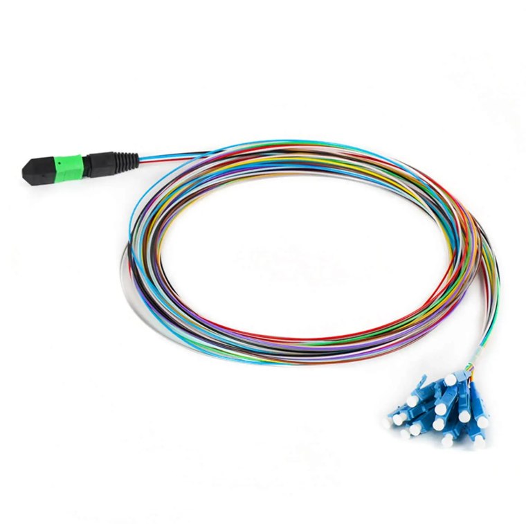
Order trunk + harness + jumpers as a matched system and polarity becomes a receiving-dock check, not a design task: Type-B trunks (label shows type, gender, P1), MPO-LC breakouts with per-leg lane labels, loopbacks for commissioning, and MPO attenuators for overloaded short spans. Every assembly is interferometer-tested per ferrule position.