UPC vs APC Fiber Connectors: Which Polish Type Do You Need?
Ask ten field techs why APC connectors are green and half will say "for PON" without being able to say why PON needs them. This guide covers the actual physics, the numbers on a datasheet that matter, and the deployment rules that prevent the two most expensive connector mistakes in the industry — cross-mating and wrong-polish attenuation.
What the Polish Actually Is
Every connector ends in a zirconia ceramic ferrule with the fiber cemented through its center. After assembly, the end-face is polished in stages (typically 5 µm → 1 µm → 0.02 µm diamond film) into a controlled geometry defined by three measurable parameters:
- Radius of curvature — the dome, 10–25 mm for PC-family polishes. The dome guarantees the fiber cores touch first, before the surrounding ceramic.
- Apex offset — how far the dome's high point sits from the fiber core center; ≤50 µm per Telcordia GR-326, ≤50 nm fiber height on our line after interferometer sorting.
- Fiber undercut/protrusion — the fiber must sit within −100 to +50 nm of the ceramic so mating pressure creates true glass-to-glass contact.
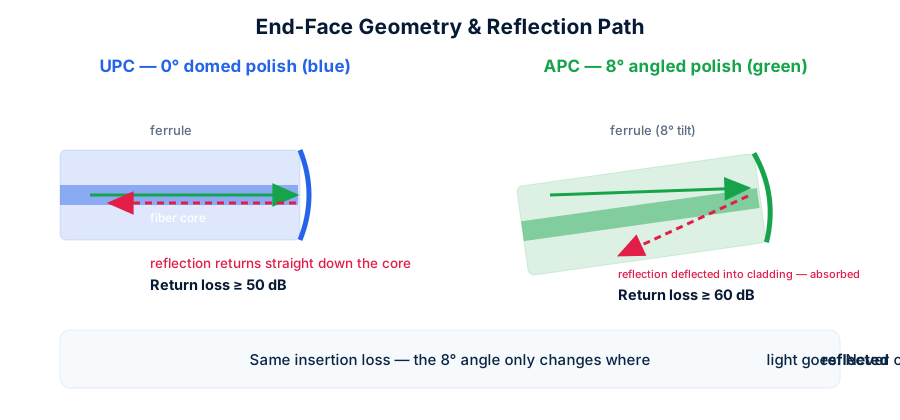
UPC (Ultra Physical Contact) is this dome polished flat-on at 0°, refined beyond the older PC/SPC grades — "ultra" refers to surface quality, not geometry. APC (Angled Physical Contact) tilts the entire dome 8° off perpendicular. That single geometric change is the whole story; everything else about the two connectors is identical.
The Physics: Where Reflections Go
At any glass boundary, Fresnel reflection sends a fraction of the light backwards — about 4% (−14 dB) at a glass-air interface, far less with good physical contact, but never zero. The question is the direction of that reflected light.
On a 0° UPC face, reflections travel straight back down the core into the transmitter. Modern DFB and EML lasers are sensitive to this back-injection: enough reflected power raises noise (RIN), destabilizes the lasing cavity, and in analog systems appears directly as picture noise. On an APC face, the 8° tilt means reflected light leaves at 16° from the fiber axis — well past the ~8.5° acceptance cone of single-mode fiber — so it enters the cladding and is absorbed within centimeters.
That is why the return-loss floor differs by an order of magnitude: ≥50 dB for UPC, ≥60 dB for APC (FOT production averages 55/65 dB). And it's why the systems that care — GPON with its RF video overlay, CATV, DWDM chains through EDFA-amplified mux/demux, high-power analog anything — standardized on APC end to end.
IL vs RL: Reading the Numbers
| Parameter | Meaning | UPC typical | APC typical |
|---|---|---|---|
| Insertion loss (IL) | Power lost passing through | ≤0.3 dB (0.1–0.2 typ.) | ≤0.3 dB (0.1–0.2 typ.) |
| Return loss (RL) | Power reflected backwards | ≥50 dB | ≥60 dB |
| Mating durability | Cycles within spec | ≥500 (IEC 61754) | |
| Operating temp | −40 ~ +75 °C | ||
Note what's equal: insertion loss. A common myth says APC "loses more light" — false for any properly polished connector. If a supplier's APC IL spec is worse than their UPC, that's a polishing-quality confession, not physics. Every FOT cord ships with individually measured IL/RL on the test label, both polishes held to the same ≤0.3 dB.
The Complete Color Code
| Housing color | Meaning | Typical fiber |
|---|---|---|
| Blue | UPC polish, single-mode | OS2 9/125 |
| Green | APC polish, single-mode | OS2 9/125 |
| Beige/black | PC/UPC multimode | OM1/OM2 |
| Aqua | UPC multimode, laser-optimized | OM3/OM4 |
| Violet (Erika) | UPC multimode | OM4 (vendor convention) |
| Lime green | UPC multimode wideband — not APC! | OM5 |
The one trap in the code: lime-green OM5 housings are UPC, not APC — multimode is never angle-polished (VCSEL sources tolerate reflections). If a green connector is on 50/125 fiber, it's OM5; on 9/125, it's APC. Our angled LC multimode cords show all three MM colors side by side.
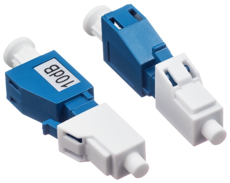
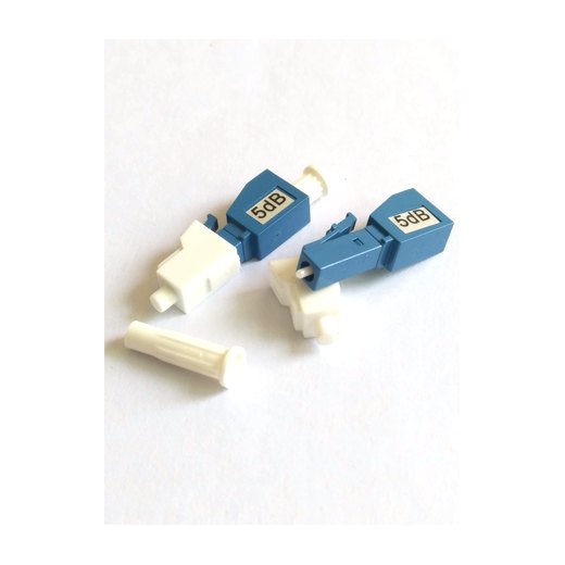
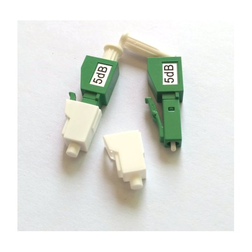
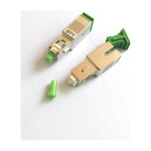
See the difference on real product — the same plug-type attenuator body in both polishes:
Application Guide: Where Each Belongs
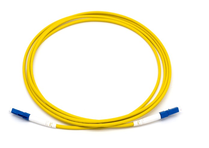
- Data center / enterprise Ethernet & SAN → UPC. Digital receivers with FEC don't care about −50 dB reflections; UPC keeps the plant simple. Standard on our LC-LC, LC-SC and LC-FC cords.
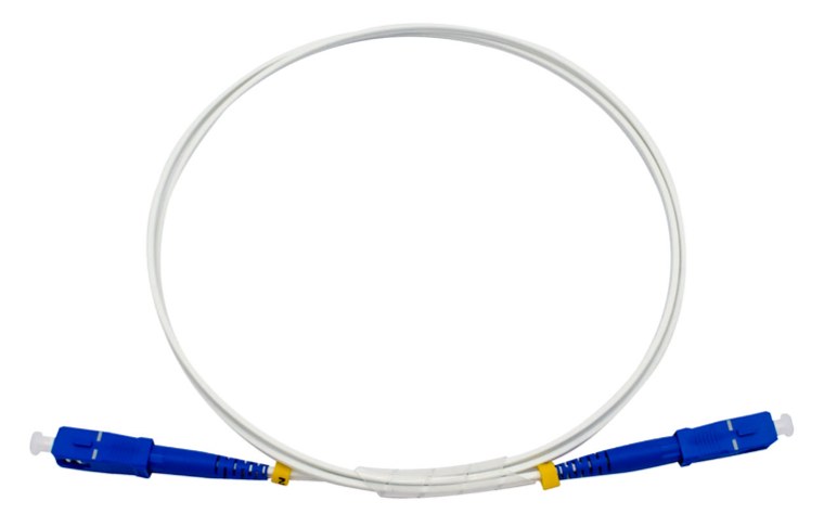
- FTTH / GPON / XGS-PON → APC everywhere. ITU-T G.984 systems carry an RF video wavelength (1550 nm) that reflections visibly degrade; GR-909 specifies APC at every splitter port. Our FTTH drop cords default to SC/APC.
- CATV headends and HFC optics → APC, same analog-video logic, usually SC/APC or FC/APC.
- DWDM long-haul → APC preferred. Cascaded EDFAs amplify reflections along with signal; multiple UPC reflection points can lase parasitically.
- Test benches → match the plant. OTDR front panels are usually UPC; launching into APC plant needs a hybrid launch cord, or you'll log a phantom −14 dB event at your own port. Keep both UPC and APC reference cords in the kit.
Mixed Plant: Hybrid Cords Done Right
Real networks mix worlds: a UPC-equipped OLT rack feeding an APC distribution frame, or UPC test gear probing PON plant. The clean solution is a hybrid patch cord — one end UPC, one end APC, each mating only its own kind. Order them deliberately labeled (we heat-shrink a polish tag at both ends) and stock them separately from standard cords; an unlabeled hybrid loose in a drawer is a future outage.
The same discipline applies to attenuation: a green APC plug-type attenuator for APC ports, blue for UPC — the attenuator mates on both faces, so polish must match on both. (Sizing and placement are covered in our attenuator selection guide.)
What Cross-Mating Physically Does
Force an 8° face against a 0° face and contact happens at one edge of the ferrule, not at the cores. Three things follow:
- An air gap at the cores — instant 2–6 dB insertion loss and a reflection spike to ~−14 dB, a thousand times worse than either connector alone.
- Edge pressure concentration — the zirconia edge chips or scores the opposing dome. This damage is permanent; the connector will underperform in every future mating, even correct ones.
- Contamination migration — chipped ceramic dust spreads to whatever the connector touches next, including adapter sleeves that then damage further cords.
If a cross-mate happens, inspect both ends with a scope before reuse; when in doubt, cut the cord. A $5 jumper is not worth a $5,000 truck roll chasing intermittent loss.
Cleaning & Inspection
Polish type doesn't change the cleaning ritual, but APC adds one wrinkle: inspection scopes need an APC-angled adapter tip to image the tilted face. The field routine that prevents 85% of connector trouble (per iNEMI studies) is simply: inspect → clean → inspect → connect — one-click pen cleaner for dry passes, lint-free wipe with fiber-grade solvent for stubborn residue, never IPA-soaked cotton and never re-using wipes. Every FOT connector leaves the factory with a full interferometer pass and arrives capped; keep the caps.
Quick Reference & FAQ
| UPC (blue) | APC (green) | |
|---|---|---|
| End-face | Domed, 0° | Domed, 8° |
| Return loss | ≥50 dB | ≥60 dB |
| Insertion loss | ≤0.3 dB — equal | |
| Home turf | Ethernet, SAN, enterprise | PON/FTTH, CATV, DWDM, splitters |
| Multimode version? | Yes (aqua/violet/lime) | No — SM only |
| Cross-mating | Never — permanent ferrule damage | |
Can I convert a UPC link to APC by swapping jumpers? Only if every mated interface in the channel changes together — adapters keep both sides captive, so audit the full path.
Is APC "better" and worth using everywhere? No — it costs slightly more, complicates test gear, and buys nothing on digital links. Use the table.