Optical Link Down: A Diagnostic Runbook for 100G, 400G and 800G
The instinct when a link goes down is to swap the module. It is the easiest thing to reach, and roughly nine times out of ten it is the wrong first move — you have disturbed a connector, introduced a new variable, and learned nothing.
There is an order that finds most faults in the first two steps, and it starts from the terminal rather than from the rack.

Work in This Order
Read the diagnostics. Decide whether the fault is in the fibre or in the equipment. Only then start touching hardware. Each step below either finds the fault or eliminates a category.
Step 1: Read DDM at Both Ends
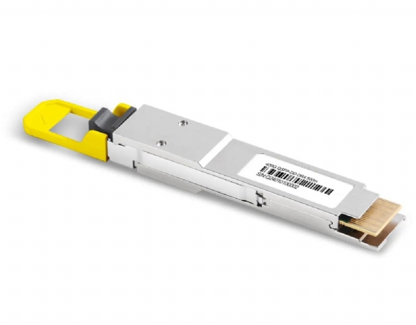
Every modern transceiver reports temperature, supply voltage, laser bias current, transmit optical power and receive optical power. Get all five, from both ends, before anything else.
No DDM at all, or the module is not recognised. This is not an optical fault. Go straight to coding and compatibility — the switch is not talking to the module.
Transmit power low or absent, bias current high. The laser is failing or has failed. Replace that module; the plant is not your problem.
Temperature near the alarm threshold. An airflow problem masquerading as an optical one. Check blanking panels, cable dress behind the switch, and whether the faceplate is smothered by DAC bundles.
Step 2: Is the Loss in the Plant?
Take the far end's transmit power and your receive power. The difference is your measured channel loss. Compare it against what the design said it should be — the link budget calculator gives you the expected figure from distance, connector count and splices.
Measured loss several decibels worse than designed. The fault is in the fibre plant. Something is dirty, bent, mis-spliced or mis-patched. Work along the channel: inspect each mated pair, check for a kinked patch cord behind a panel, and confirm the patching actually goes where the label says.
Receive power far too high. Genuinely common on short links with long-reach optics, and it produces errors that look like a fault. The receiver is overloaded. Fit a fixed attenuator sized to bring the power inside the operating window.
Measured loss matches the design. The fibre is fine. Move on — and resist the temptation to re-terminate something.
Step 3: Errors With Normal Power
This is the case that wastes the most time, because everything looks healthy. Optical power is correct at both ends and the link still errors or flaps.
Look at pre-FEC bit error rate. On a PAM4 link, pre-FEC errors are normal — a rate of one in a million is a healthy 400G link. What matters is the number relative to the FEC correction limit, and the direction it is moving.

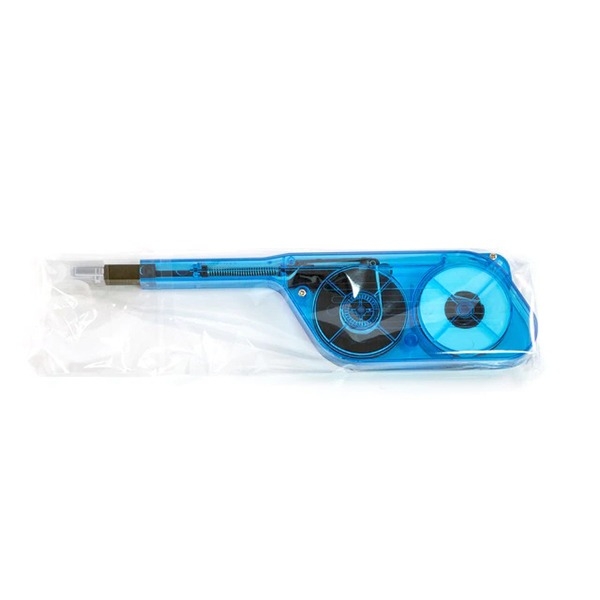
A pre-FEC BER climbing toward 1e-4 with normal optical power almost always means contamination on an end face, or a connector that has been disturbed and not reseated properly. Clean and inspect both ends — see the inspection procedure — and watch whether the rate drops.
Step 4: Isolate With a Loopback
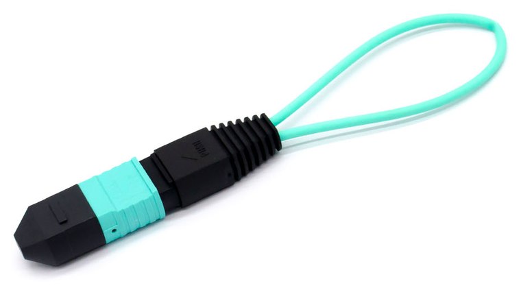
If the fault survives the first three steps, remove the fibre plant from the equation. A loopback module returns each transmit lane to its paired receive inside a single plug, so the port is talking to itself.
Loopback clean. The switch port and the module are healthy. The fault is in the plant, and you missed something in step 2 — go back and check the patching, not the fibre.
Loopback errors too. The problem is the module or the switch port. Try the module in a different port and a different module in the same port; two tests separate them definitively.
One trap: a zero-loss loopback on a long-reach optic overloads its own receiver and produces errors that are not a fault. Use an attenuated loopback for anything ER or ZR class.
Step 5: The Faults That Are Not Physical
If the optics and the plant are clean, the remaining causes are configuration, and they are worth checking early if the link has never worked rather than having failed in service.
Breakout mode. A port configured as one 400G interface will not talk to a device expecting 4×100G. Reconfiguration usually requires a reload — the breakout configurator shows what each ratio actually needs.
FEC mismatch. Both ends must agree. Some platforms negotiate, some do not, and a mismatch produces a link that comes up and immediately errors.
Polarity. On a new parallel link that has never worked, polarity is the leading suspect. Light is present, it is simply arriving on the wrong fibres.
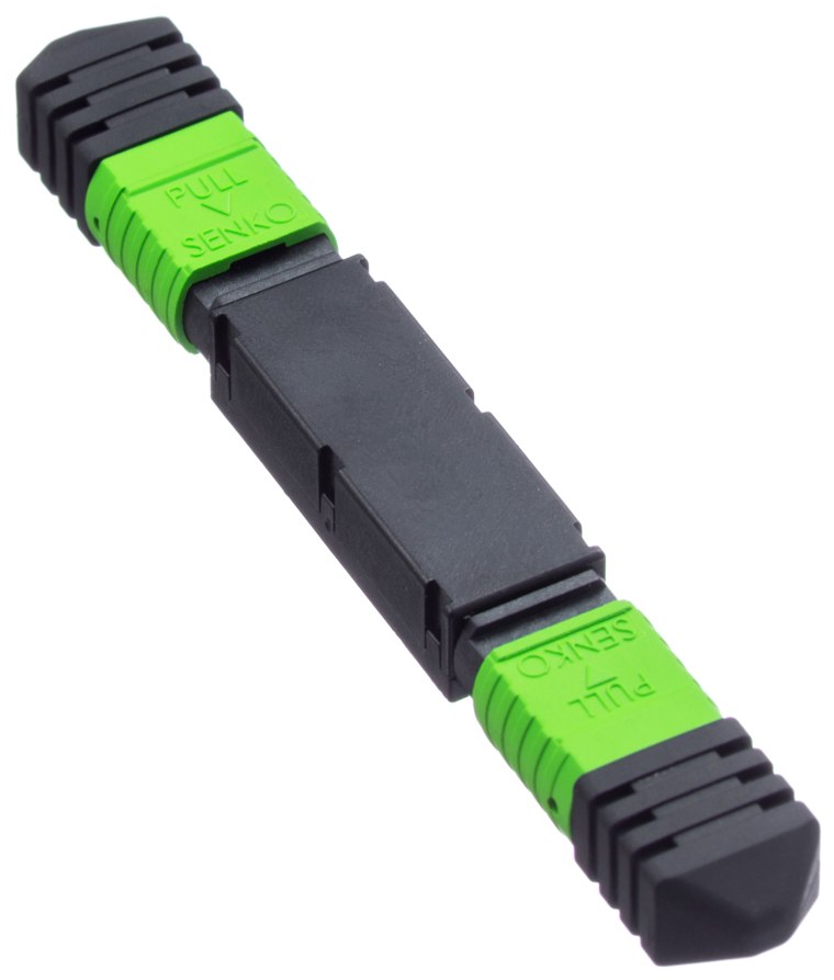
Wrong optic for the fibre. An SR module on single-mode fibre, or a DR4 on multimode. It happens more than anyone admits, particularly where both plants use MPO connectors of the same shape.
FAQ
What Rx power should I expect? Far-end Tx power minus the channel loss. There is no universal number — that is why you compute the expected value rather than comparing against a remembered one.
The link works but throughput is poor. That is usually not a physical-layer fault. On an RDMA fabric, check the congestion control configuration before the optics.
Should I keep spare modules on the shelf? Yes, and a couple of OEM ones too. Being able to swap and prove is worth far more than the cost of the spares when a fault is disputed.
The link flaps intermittently rather than failing. Almost always thermal or a marginal connector. Watch DDM temperature over a day, and reseat and inspect every mated pair in the channel.