GPON FTTH Build-Out: Specifying Drop Cable, PLC Splitters and PON Optics
A planning guide for ISPs moving subscribers from copper to fibre. Written for the engineer who has to turn a coverage map into a bill of materials — and defend every line of it.
Why the BOM matters more than the OLT
Copper access is being switched off across the emerging FTTH markets. Uzbektelecom, for example, stopped connecting new ADSL/VDSL subscribers in August 2025 and now provisions every new line on GPON or FTTB at 100 Mbit/s or better; similar migrations are under way across Central Asia and the South Caucasus. Every one of them produces the same document: a tender for OLTs and an afterthought spreadsheet for "passive materials".
That spreadsheet is where the network is actually won or lost. The OLT is a commodity with a datasheet. The outside plant — the splitters, the drop cable, the connectors, the splice count — is what decides whether a Class C+ port serves 32 homes at 20 km or 64 homes at 10 km, and whether the last 50 m to the wall survives five winters.
This article covers the three passive decisions that most often go wrong, in the order the loss budget forces you to make them:
- Which optical class you are designing to (that fixes the budget).
- How to spend the budget on splitters (that fixes the topology).
- What is left for cable, connectors and splices — and what the drop cable must therefore be.
Everything here is vendor-neutral and traceable to ITU-T G.984 / G.9807 / G.657 or to published component specifications.
1. The loss budget is the specification
A PON has no amplifiers. Whatever the OLT launches must reach the ONU after passing a splitter, 10–20 km of fibre, several connectors and a dozen splices — and the ONU's reply must survive the same path back. ITU-T therefore defines optical distribution network (ODN) classes: a minimum and maximum optical path loss that the transceivers at both ends are guaranteed to tolerate.
Table 1 — ODN loss classes you will actually be offered
| System | Class | Optical path loss (min–max) | Downstream / upstream λ | Where it is defined |
|---|---|---|---|---|
| GPON | B+ | 13–28 dB | 1490 / 1310 nm | G.984.2 Amd 1 (2006), now Appendix III of G.984.2 (2019) |
| GPON | C+ | 17–32 dB | 1490 / 1310 nm | G.984.2 Amd 2 (2008), now Appendix V |
| GPON | D | 20–35 dB | 1490 / 1310 nm | G.984.2 (2019) Appendix V |
| GPON | "C++" | vendor label, 33–35 dB claimed | 1490 / 1310 nm | not an ITU-T class — see below |
| XGS-PON | N1 | 14–29 dB | 1577 / 1270 nm | G.9807.1 |
| XGS-PON | N2 | 16–31 dB | 1577 / 1270 nm | G.9807.1 |
| XGS-PON | E1 | 18–33 dB | 1577 / 1270 nm | G.9807.1 |
| XGS-PON | E2 | 20–35 dB | 1577 / 1270 nm | G.9807.1 |
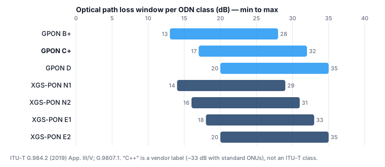
Three things to take from the table:
- The class describes the pair, but the extension is one-sided. A C+ OLT SFP launches +3 to +7 dBm and receives down to −32 dBm; a C+ ONU launches +0.5 to +5 dBm (the same as B+) and receives down to −30 dBm (B+: −27 dBm). Put B+ ONUs behind a C+ OLT and the upstream still has its 32 dB; the downstream drops to about 29–30 dB. The network is better than B+ but not C+. Design to the weaker direction.
- The minimum matters too. A Class C+ receiver is overloaded above about −12 dBm (OLT) / −8 dBm (ONU). Every ONU closer than the minimum loss needs an attenuator or a higher split — which is why planners put the splitter as close to the homes as the budget allows.
- "C++" is a marketing term. Modules sold as C++ typically launch +4.5 to +10 dBm with a receiver at −32 or −33 dBm. With a standard ONU launching +0.5 dBm minimum, that gives an upstream budget of about 33 dB — not 35. A true 35 dB budget needs the Class D receiver (−35 dBm). Ask for launch power, sensitivity and overload in dBm and design to those numbers, not to the letters.
XGS-PON on the same fibre. XGS-PON uses 1577 nm down and 1270 nm up, so it can share the ODN with GPON through a WDM1r coexistence filter at the OLT. Budget 1.0–1.5 dB for the filter, and note that fibre attenuation at 1270 nm (0.40–0.47 dB/km planning value) is higher than at 1310 nm. An ODN built today right up to the Class C+ limit (32 dB) will carry XGS-PON Class E1 (33 dB) later — and N2 (31 dB) only if the ODN actually measures under 31 dB. An ODN built "just inside" B+ will normally be fine for N1/N2, but only because it has no splitter headroom to lose.
2. Spend the budget on splitters first
The splitter is the single largest loss in the network, and it is the one loss that does not depend on distance. The planning number is the datasheet maximum insertion loss over 1260–1650 nm, not the theoretical 10·log₁₀(N).
Table 2 — PLC splitter loss, theoretical vs. what you should plan with
| Split | Theoretical (10·log N) | Typical datasheet max IL | Uniformity max |
|---|---|---|---|
| 1×2 | 3.0 dB | ≤ 3.8–4.0 dB | ≤ 0.4–0.6 dB |
| 1×4 | 6.0 dB | ≤ 7.1–7.3 dB | ≤ 0.6–0.7 dB |
| 1×8 | 9.0 dB | ≤ 10.2–10.5 dB | ≤ 0.8 dB |
| 1×16 | 12.0 dB | ≤ 13.5–14.0 dB | ≤ 1.0–1.2 dB |
| 1×32 | 15.0 dB | ≤ 16.5–17.2 dB | ≤ 1.5 dB |
| 1×64 | 18.0 dB | ≤ 20.5–21.0 dB | ≤ 2.0 dB |
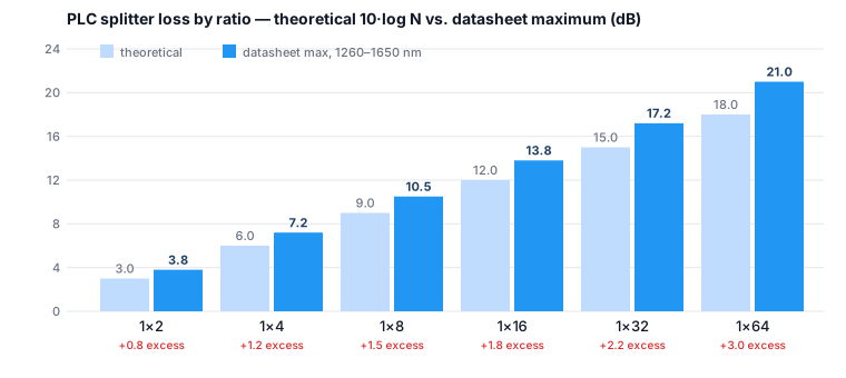
The gap between the columns — 1.2–1.5 dB at 1×8, 2.5–3 dB at 1×64 — is excess loss, and cheaper wafers sit at the top of the range. Two rules follow:
Rule 1: 1×32 is the natural ceiling for Class B+; 1×64 needs C+. With a 1×32 at 17.2 dB and 3 dB of design margin, a B+ port (28 dB) has 7.8 dB left for everything else. Take out about 3.8 dB of connectors, splices and bends (the count used in section 5) and the remaining 4 dB buys 10 km at a planning figure of 0.40 dB/km. Put a 1×64 (21 dB) on the same B+ port and you are left with 4 dB before connectors — well under a kilometre once they are counted, and no allowance for a repair splice. On a C+ port the same 1×64 leaves 8 dB, which is why C+ optics and 1×64 splitters tend to be bought together.
Rule 2: cascading costs about 1 dB. A 1×4 in the cabinet feeding 1×8s in the building (4 × 8 = 32) gives the same subscriber count as a single 1×32, but two datasheet maxima (7.2 + 10.5 = 17.7 dB) add about 0.5 dB of excess over one 1×32 (17.2 dB), and the second splitter usually brings one more connector pair (0.5 dB). Cascaded ("distributed") splitting wins when homes are scattered along a road and feeder fibre is expensive; centralised splitting wins in dense urban blocks and makes fault-finding with an OTDR far easier because every ONU has the same loss profile.
What to write in the splitter spec:
- Split ratio and input configuration (1×N or 2×N — 2×N gives a protection input for ring feeders).
- Maximum insertion loss at 1260–1650 nm including connectors, uniformity, PDL (≤ 0.3 dB up to 1×16, ≤ 0.35 dB for 1×32/1×64), return loss ≥ 55 dB (≥ 50 dB acceptable with UPC), directivity ≥ 55 dB.
- Operating temperature: −40 to +85 °C if the splitter lives in a street cabinet or pole closure; −20 to +70 °C is an indoor spec.
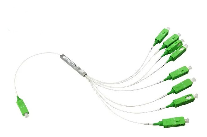
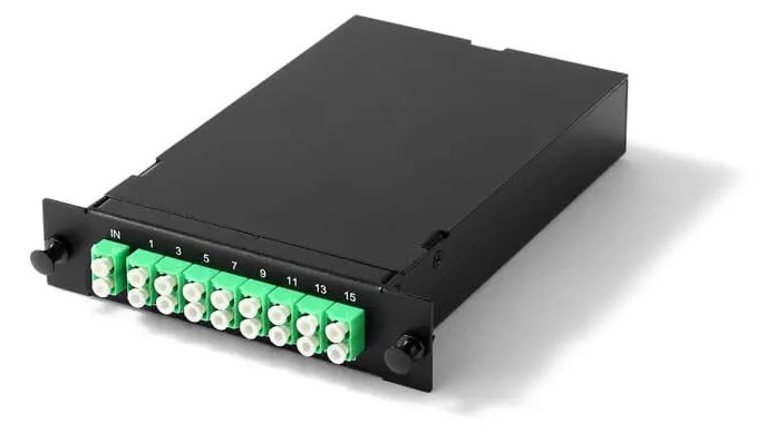
- Package: bare/steel-tube (for splice-in closures), ABS box with pigtails (for wall boxes), LGX/plug-in cassette (for ODF and cabinets), 1U rack (for the central office). Do not accept "ABS module" for a pole closure.
- Connectors on the outputs: SC/APC for any network that will ever carry RF video overlay or XGS-PON — see section 4.
- Fibre grade inside the package: G.657.A1 minimum; A2 for compact cassettes.
- A per-unit test report listing IL on every output at 1310 / 1490 / 1550 nm, and the serial number on the label.
3. What is left decides the drop cable
After the splitter and the margin, the residual budget is spent on fibre, connectors and splices. Planning values that survive contact with real plant:
| Element | Planning value | Note |
|---|---|---|
| G.652.D / G.657.A fibre, 1310 nm | 0.35–0.40 dB/km | G.652.D limit 0.40; good cable is specified at 0.35 |
| G.652.D / G.657.A fibre, 1490/1550/1577 nm | 0.25–0.30 dB/km | G.652.D limit 0.30 at 1550; good cable 0.22 |
| Fibre at 1270 nm (XGS-PON upstream) | 0.40–0.47 dB/km | the tightest wavelength |
| Fusion splice | 0.10 dB | 0.05 typical, 0.10 planning |
| Mechanical / field-installable connector | 0.30–0.50 dB | budget 0.5 |
| Factory-terminated SC/APC (pigtail or pre-connectorised drop) | 0.20–0.30 dB | budget 0.3 |
| Macro-bend allowance in closures and wall boxes | 0.5 dB total | see G.657 table below; raise it for 1577 nm |
| Design / ageing / repair margin | 2–3 dB | never below 2 |
The drop cable is the last 30–80 m from the distribution box to the subscriber. It is the cheapest cable per metre and the most expensive to replace, because it is installed once per household, by the least experienced crew, in the most exposed position. It therefore has to be chosen on three criteria, not on price:
3.1 Construction: bow-type indoor vs. self-supporting outdoor
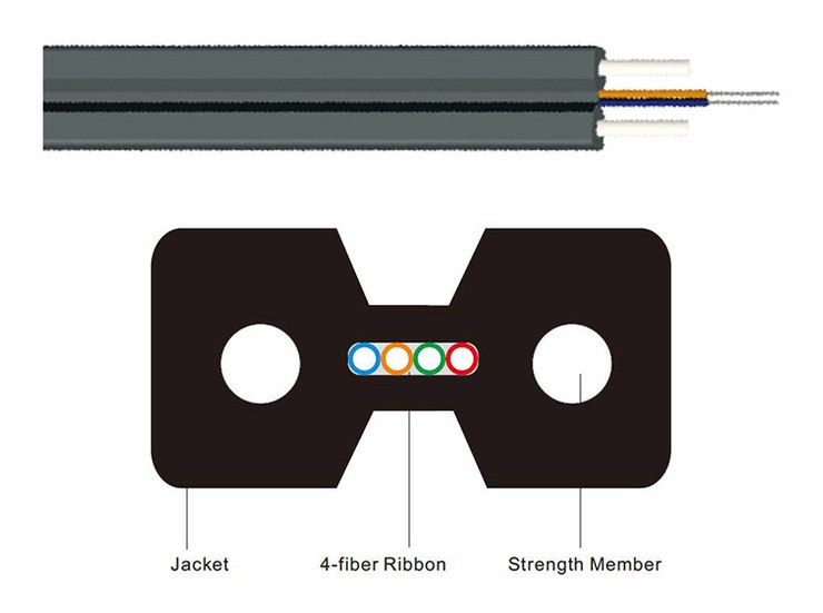
Drop cables in this market follow the Chinese YD/T 1997.1 "butterfly" (bow-type) family. The model codes are not formally standardised but are commonly decoded as G = communication cable, J = indoor, Y = outdoor, X = bow-type, F = non-metallic strength member, C = self-supporting, H = LSZH sheath — so:
| Code | Meaning | Typical section | Strength member | Tensile, long / short term | Use |
|---|---|---|---|---|---|
| GJXFH | indoor bow-type, non-metallic | 2.0 × 3.0 mm | 2 × FRP rods | 40 / 80 N | inside buildings, riser to flat, wall runs |
| GJXH | indoor bow-type, metallic | 2.0 × 3.0 mm | 2 × steel wires | 100 / 200 N | as above where extra pull strength is needed |
| GJYXCH | outdoor bow-type, self-supporting | 2.0 × 5.0–5.3 mm | 2 × FRP or steel + Ø1.0–1.2 mm steel messenger | 300 / 600 N | pole-to-house aerial spans |
| GJYXFCH | outdoor self-supporting, non-metallic | 2.0 × 5.0–5.3 mm | FRP + FRP messenger | 300 / 600 N | aerial spans near power lines / lightning-prone areas |
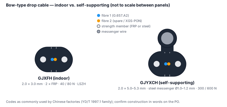
Because the letters are read differently by different factories, write the construction out in words on the purchase order — strength member material, messenger material and diameter, sheath compound — and do not rely on the code.
The self-supporting variant carries a messenger that takes the load across the span; the flat section peels away at the wall so the indoor part can be routed without the messenger. Typical span 50–80 m depending on the messenger and local wind/ice load. Aerial spans must use the self-supporting cable. Indoor GJXFH strung between poles is the most common single cause of drop failures in new FTTH networks: a 40 N cable is asked to carry a span load, the fibre creeps, and the attenuation climbs every winter until the link drops.
Fibre count: 1 fibre is enough for a residential GPON drop, but a 2-fibre drop costs almost nothing more and gives you a spare for a fault, a second service, or an XGS-PON overlay on a separate fibre later. Most operators standardise on 2F.
3.2 Fibre grade: G.657 and why the letter matters
Drop cable is coiled in wall boxes, stapled round door frames and bent through 90° at the ONU. Standard G.652.D fibre is only specified to a 30 mm bend radius; drop cable must be G.657.
Table 3 — G.657 macrobend loss limits (ITU-T G.657, 08/2024; one full turn unless stated)
| Grade | Radius | Max added loss at 1550 nm | at 1625 nm |
|---|---|---|---|
| G.652.D | 30 mm (100 turns) | — | 0.1 dB |
| G.657.A1 | 15 mm (10 turns) | 0.25 dB | 1.0 dB |
| G.657.A1 | 10 mm | 0.75 dB | 1.5 dB |
| G.657.A2 | 15 mm (10 turns) | 0.03 dB | 0.1 dB |
| G.657.A2 | 10 mm | 0.10 dB | 0.20 dB |
| G.657.A2 | 7.5 mm | 0.50 dB | 1.0 dB |
| G.657.B3 | 10 mm | 0.03 dB | 0.1 dB |
| G.657.B3 | 7.5 mm | 0.08 dB | 0.25 dB |
| G.657.B3 | 5 mm | 0.15 dB | 0.45 dB |
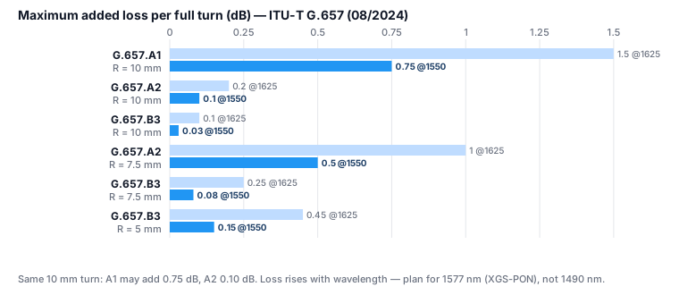
Two practical consequences:
- Specify A2, not A1, for drop cable. The price difference is small; at the specification limit, one full turn at 10 mm radius is allowed 0.75 dB on A1 fibre and 0.10 dB on A2 — 7.5 times less. Real A1 fibre usually measures better than its limit, but you are buying the guarantee, not the sample. Bend loss also rises with wavelength (look at the 1625 nm column), so a network that is comfortable at 1490 nm today loses margin at 1577 nm when XGS-PON arrives.
- Category A is fully G.652.D-compliant; category B is not necessarily. In the current edition both categories share the same nominal mode-field diameter range (8.6–9.2 µm), so the old "B3 won't splice to G.652.D" warning is out of date; the remaining differences are in chromatic dispersion and PMD, and splice loss to G.652.D depends on the particular fibre's index profile. B3 is excellent in a wall box or an indoor patch lead. For the cable you fusion-splice into the distribution network, A2 keeps every parameter identical to the feeder and removes a variable from your OTDR traces.
3.3 Sheath and environment
- LSZH for anything that enters a building; PE (black, UV-stabilised) for outdoor-only runs. Many self-supporting drops are supplied with a black LSZH sheath that does both jobs — confirm UV resistance (ISO 4892 or equivalent) on the datasheet rather than assuming it.
- Operating temperature −40 to +70 °C for Central Asian and Caucasus climates; check the installation temperature too (some LSZH compounds are brittle below −10 °C).
- Ask for the factory OTDR trace per drum and a drum length that matches your average span with a service loop — 1 km and 2 km drums for aerial drop, 500 m for indoor.
4. Connectors: SC/APC, and why
ITU-T G.984 does not prescribe a connector; SC/APC (8° angled end face) at the ONU and throughout the ODN is industry practice and is written into most operator and national FTTH specifications. Two reasons:
- Return loss. G.984.2 requires the ODN to present an optical return loss of at least 32 dB at both the OLT and the ONU interface. An unmated fibre end reflects about 4 % of the light (−14 dB, the Fresnel reflection of glass to air); a dirty or damaged mated UPC connector sits somewhere between that and its −50 dB specification; a mated APC connector reflects less than −60 dB. Reflections do not just cost budget — they destabilise the DFB laser in a Class C+ OLT and produce errors that look like a bad splitter.
- RF video overlay and XGS-PON. Any 1550 nm analogue overlay is intolerant of reflections, and 10G optics are more sensitive to them than 2.5G.
For the drop itself you have two choices. Pre-connectorised drop cable (factory SC/APC on one end, IL ≤ 0.3 dB, with an individual test report) is faster to install and gives a predictable loss, but you must plan drum lengths. Field-installable "fast" connectors cost less per unit and fit any length, but their IL is 0.3–0.5 dB, they need a good cleaver and a trained crew, and they are the first place to look when a subscriber's power level drifts. A common compromise is a pre-terminated end at the subscriber (where the connector is handled least) and a fusion splice at the distribution box.
5. A worked budget
Design case: Class C+ optics, centralised 1×32 splitting in a street cabinet, 12 km from OLT to the farthest ONU, aerial drop, drop fusion-spliced at the distribution box and terminated at a wall socket.
| Loss element | Quantity | Unit value | Total |
|---|---|---|---|
| Feeder + distribution + drop fibre, 1310 nm (worst GPON wavelength) | 12 km | 0.40 dB/km | 4.8 dB |
| 1×32 PLC splitter (datasheet max) | 1 | 17.2 dB | 17.2 dB |
| Connector pairs: ODF, splitter in, splitter out, wall socket, ONU | 5 | 0.5 dB | 2.5 dB |
| Fusion splices: 3 feeder drum joints, cabinet in/out, distribution box, drop both ends | 8 | 0.1 dB | 0.8 dB |
| Bend allowance (closures, wall box) | — | — | 0.5 dB |
| Sub-total | 25.8 dB | ||
| Design margin | 3.0 dB | ||
| Total planned loss | 28.8 dB |
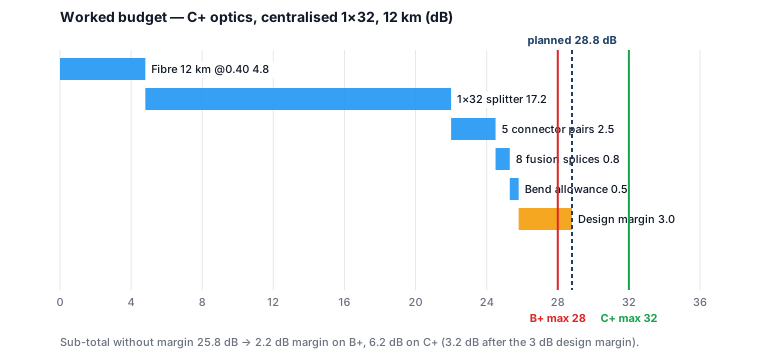
Against a Class C+ maximum of 32 dB this leaves 3.2 dB unspent — enough to extend the feeder by about 8 km, or to absorb three repair splices and a dirty connector. Against Class B+ (28 dB) the same plant fits with 2.2 dB of margin instead of 3.0: acceptable for underground urban plant with pre-terminated drops, thin for aerial plant in a cold climate. The planner would either accept the thinner margin, shorten the feeder by 2 km, or specify C+ optics.
Change one variable at a time and the trade-offs become visible (C+ optics, 3 dB margin, the same 3.8 dB of connectors, splices and bends, 0.40 dB/km):
| Scenario | Splitter loss | Budget left for fibre | Max fibre length |
|---|---|---|---|
| Dense urban, 1×64 centralised | 21.0 dB | 4.2 dB | ≈ 10 km |
| Suburban, 1×32 centralised | 17.2 dB | 8.0 dB | ≈ 20 km |
| Rural road, 1×4 → 1×8 cascaded | 17.7 dB + 0.5 dB extra connector | 7.0 dB | ≈ 17 km |
| Rural, 1×16 centralised | 13.8 dB | 11.4 dB | ≈ 28 km* |
*G.984.2 sets the nominal maximum fibre distance at 20 km (logical reach 60 km); the C+/Class D appendix allows up to 60 km of fibre, but check that the OLT's ranging window is configured for it.
XGS-PON overlay on the suburban case: add 1 dB for the WDM1r filter and recalculate at 1270 nm (0.45 dB/km): 12 km × 0.45 + 17.2 + 2.5 + 0.8 + 0.5 + 1.0 + 3.0 = 30.4 dB. Inside Class E1 (33 dB), just inside N2 (31 dB), outside N1 (29 dB). That is the argument for building the ODN to C+ numbers now even if the first OLT is B+.
6. The RFQ checklist
Copy this into the tender. If a bidder cannot answer a line, that is the answer.
OLT / ONU optics - Class (B+, C+, D; N1/N2/E1) and launch power, sensitivity and overload in dBm from the datasheet, for both the OLT and the ONU side - Wavelengths and whether a WDM1r coexistence port is required - DDM supported; OLT SFP compatibility with your chassis vendor stated in writing
PLC splitters - Ratio, 1×N or 2×N, package type, connector type (SC/APC), fibre grade - Max IL at 1260–1650 nm, uniformity, PDL, RL, directivity, operating temperature - Per-unit IL report at three wavelengths, serial-numbered
Drop cable - Construction in words (bow-type indoor / self-supporting outdoor), fibre count, fibre grade (G.657.A2), section dimensions - Strength member material; messenger material and diameter; long-term and short-term tensile rating; minimum bend radius - Sheath material, UV resistance, operating and installation temperature range - Drum lengths, sheath printing (operator name + metre marks), per-drum OTDR trace
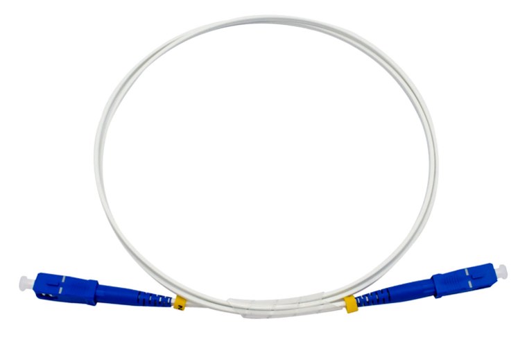
Connectivity - Pre-connectorised drop or field connectors; IL and RL per connector with test method - Pigtails and patch cords: SC/APC, G.657.A2, per-cord IL/RL report
FAQ
Can I run 1×64 on Class B+ if the homes are close? On paper: 28 dB − 21 dB splitter − 3.8 dB of connectors, splices and bends leaves 3.2 dB — about 8 km of fibre with zero margin, or under 1 km with a proper 3 dB margin. In practice the answer is no; one repair splice or a dirty connector takes the link down. Use C+ optics for 1×64.
Is Class C++ real? The letters are a vendor label; the numbers behind them (typically +4.5 to +10 dBm launch, −32 to −33 dBm sensitivity) are real and give about 33 dB with standard ONUs. A 35 dB budget is Class D and needs a −35 dBm OLT receiver. Buy the numbers, and make sure the ONUs match.
FRP or steel strength members in the drop? Steel is cheaper and stronger; FRP is dielectric. Use FRP (GJXFH / GJYXFCH) wherever the drop runs near power lines, enters a building without a bonding point, or is in a lightning-prone area. Steel-messenger GJYXCH is fine for most aerial spans where earthing is straightforward.
G.657.A1 is what my supplier stocks. Is it acceptable? For distribution cable in ducts, yes. For drop cable that will be coiled in wall boxes, insist on A2 — the guaranteed loss for a full turn at 10 mm is 7.5 times lower.
Do I need SC/APC on the OLT side too? The OLT SFP itself is usually SC/UPC or LC/UPC; the ODF and everything after it should be APC. Never mate APC to UPC — it damages both ferrules and reflects more than either.
How much margin is enough? 3 dB for a new build in a cold climate with aerial plant; 2 dB is defensible for underground urban plant with pre-terminated drops. Below 2 dB you are designing the network to fail at its first repair.