Incoming QC for Optics: The Nine Checks Before You Deploy
A pallet of transceivers arrives — two hundred to two thousand modules, each destined for a production port, plugged in by an engineer with no way to tell a good one from a marginal one by looking at it. The failures that matter are not the dead-on-arrival ones; those announce themselves in thirty seconds. They are the module that links, passes traffic and runs a pre-FEC error rate one decade from the correction limit, then fails four months later on a Sunday.
Incoming QC catches those first. Worth doing for any supplier you have not built years of history with, and on every batch from one you have — because what changes silently is not the design but a component substitution three tiers down the supply chain. Nine checks follow, cheapest failures first.

Checks 1 and 2: Label, Packaging, EEPROM Identity
Check 1 — label and packaging. Thirty seconds per box, and it catches more than anyone expects. Carton part number matching the purchase order; anti-static bags sealed rather than resealed; a serial list matching the physical serials rather than quoting a range; dust caps on every port; a module label carrying standard, wavelength, reach and serial.
Reject the shipment, not the module, if serials are duplicated, bags have been opened, or the label shows a different reach class from the order. A mixed batch is a supply-chain signal.
Check 2 — EEPROM identity. Read the module's own description of itself and compare it field by field against the order. The layout follows the form factor: SFF-8472 for SFP through SFP28, SFF-8636 for QSFP+ and QSFP28, CMIS above that. In SFF-8472 the A0h page puts the identifier at byte 0, connector type at 2, vendor name at 20–35, OUI at 37–39, part number at 40–55, serial at 68–83, date code at 84–91 and checksums at 63 and 95. Six fields are worth comparing every time.
| Field | What it should say | What a mismatch means |
|---|---|---|
| Identifier and connector type | The form factor and connector you ordered | Wrong part entirely, or a re-labelled body |
| Vendor name and OUI | Exactly the string your platform expects | The switch will warn or hold the port down |
| Vendor part number | The platform's own part number, character for character | Coded for another model or software train |
| Serial number and date code | Unique per module, plausible and recent | Duplicated serials mean re-used or re-flashed stock |
| Wavelength and reach codes | The standard you ordered | Host picks the wrong FEC mode and never links |
| Checksums | Valid | Incomplete or corrupt programming — reject on sight |
Duplicated serials are the most damning finding here. They make warranty tracking impossible and usually mean the coding was applied in bulk without per-module programming — which raises the question of what else was done in bulk.
Checks 3 and 4: Recognition and DDM Sanity
Check 3 — recognition in the actual target switch. Not a similar switch: the exact model running the exact software version the module will live under, because acceptance lists and CMIS handling change between trains, and a module accepted on one release can be rejected on the next.
You want the interface to appear, the module type reported correctly, no warning on insertion, and the port up in the mode you intend to use. A module that links at 1×400G but refuses a 4×100G breakout is telling you about its CMIS application list; the unsupported-transceiver guide covers what each platform does.
Check 4 — DDM sanity. Read all five digital diagnostics values — case temperature, supply voltage, laser bias, transmit power, receive power — against the module's own warning and alarm thresholds, which live in its EEPROM. Those are the manufacturer's own numbers, so this is a self-consistency test as much as a performance one. Three findings should worry you.
Any value inside specification but within a decibel of its own warning threshold. A new module should sit mid-window, with headroom left for ageing, temperature and a dirty connector.
Transmit power spread across the batch. Record it and look at the distribution. A tight cluster is a controlled process; a bimodal one, or a tail two decibels below the rest, means two builds went into one box.
Bias current high relative to the batch. Laser bias climbs over a device's life, so a new module already at the top of its batch has less life left than its neighbours.
Do not over-read absolute numbers: SFF-8472 asks only for ±3 dB on optical power, and ±3 °C, ±3 per cent and ±10 per cent on the other three. Comparison beats any single reading.
Checks 5 and 6: Loopback and the Pre-FEC Soak
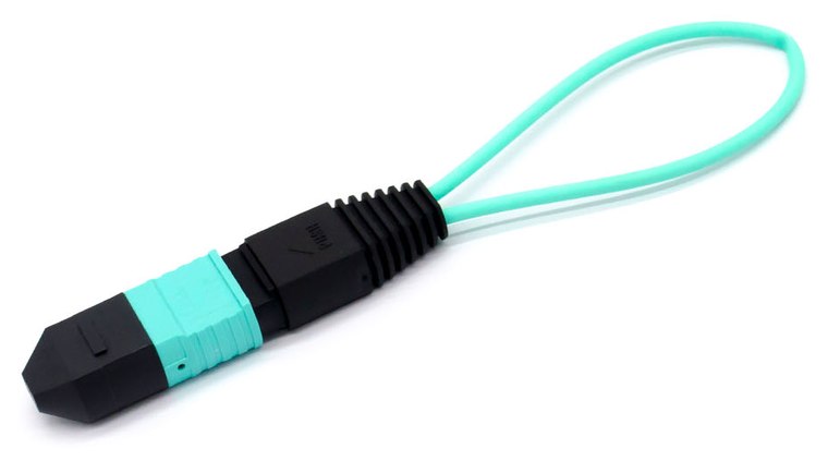
Check 5 — loopback. A loopback module returns each transmit lane to its paired receive lane, so the module talks to itself with no plant in the experiment. For eight-fibre optics in an MPO-12 the map is 1↔12, 2↔11, 3↔10 and 4↔9, positions 5–8 dark; a sixteen-fibre application folds about the centre, 1↔16 through 8↔9. The wrong map produces a port that comes up on some lanes and not others, so keep the right MPO loopback labelled and to hand.
What it proves: the host SerDes and the module's transmit and receive chains work together with the plant removed. What it does not prove: anything about link budget, because a zero-loss loop is not a real channel. On a long-reach module it misleads — a 10GBASE-ER transmitter can launch +4 dBm into its own receiver, above what that receiver accepts. Use an attenuated loopback above the FR class or you will read overload as a module fault.
Check 6 — the pre-FEC error soak. This separates a real acceptance test from a plugging-it-in exercise, and it is the only check that catches the marginal module. Run traffic for hours, not minutes, watching the pre-FEC counter rather than the interface error counter. On a PAM4 link, pre-FEC BER between 1e-6 and 1e-5 is normal and is not a fault: KP4 FEC — RS(544,514) — corrects up to about 2.4e-4. What matters is margin and direction, not the absolute value.
Run the soak in the target platform and, if you can, over a representative length of the fibre you intend to use. A pristine two-metre jumper flatters everything.
Checks 7 and 8: End Faces and Thermal Soak
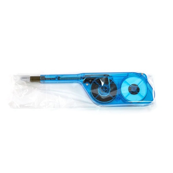
Check 7 — inspect and clean before anything is mated. The rule has no exceptions: inspect first, clean second, mate third. A contaminated ferrule mated once transfers its contamination to the port it touched, and now you have two problems and a module that will be blamed for both. IEC 61300-3-35 gives the criteria by zone; the MPO cleaning and inspection guide covers procedure and geometry.
Multi-fibre ferrules make this non-negotiable. Twelve or sixteen end faces sit behind one connector, invisible without a scope with an MPO tip, and one contaminated position produces exactly the symptom — one lane errored, the rest clean — that people spend a day chasing in switch configuration. A scope and cleaner kit pays for itself the first time it is used in anger, and new modules are not exempt: dust caps are dust caps, not clean rooms.
Check 8 — thermal soak in a loaded chassis. A module tested alone, in a lab at 22 °C, in a switch with three ports populated, is tested under conditions that will never occur again. Populate the chassis, run it at the ambient the room actually reaches, and leave traffic running for hours.
Watch two things: case temperature climbing toward the module's high-temperature alarm, and pre-FEC BER as a function of it. A module whose error rate is stable cold and rises measurably as the case warms is thermally marginal, and it will fail in the hottest cage in the hottest rack in July. Low-density lab testing reliably misses this, which is why the check exists. The power and thermal calculator gives what a full faceplate has to dissipate — usually more than the room's design assumed.
Check 9: How Many Do You Actually Test
Nine checks at fifteen minutes each does not scale to two thousand modules, so the last decision is how many go through the process. Two answers are defensible; one is not.
100 per cent, for critical links. Spine uplinks, long-reach modules with no spare in the building, anything crossing a leased duct or going to an unstaffed site. The module cost is trivial against the site visit, and the correct sample size is all of them.
A sampling plan, for volume. ISO 2859-1 — the same standard as ANSI/ASQ Z1.4 — converts a lot size and an accept quality limit into a sample size and an accept number. At general inspection level II, the default, a lot of 501 to 1200 gives code letter J and a sample of 80. Level III raises the sample when a supplier is on watch; level I lowers it once they have earned it.

The indefensible answer is to test the first three out of the box. That is not a sample: the first three are not random and are frequently the ones the supplier put on top. Pull from different cartons, at random, and record which serials were tested.
One refinement. Do the fast checks — label, EEPROM, recognition, DDM — on every module: two minutes each, and they catch the identity and coding faults behind most real rejects. Reserve the sampling plan for the soak and the thermal run.
What a Manufacturer Tests Before It Ships
Incoming QC exists because outgoing QC is not universal. Knowing what a serious factory does tells you what you are duplicating and what you are adding.
On our line in Shenzhen every module — not a sample — is programmed, read back and verified against the target platform's expected strings, so the identity check on arrival should find exactly what the order specified. Every module is measured optically over its temperature range: transmit power, extinction ratio, receiver sensitivity and the eye-quality metrics the class calls for, including TDECQ where the standard requires it. Every module is then traffic-tested in the actual target switch model rather than a reference board. End faces are inspected before packing and test records are held against serial numbers. Every fibre in every MPO trunk and harness is measured individually too, because a sixteen-fibre assembly with one bad position is indistinguishable from a good one until it is in a rack.
What we cannot do from here is test in your chassis at your density and your ambient temperature. That is what checks 3, 6 and 8 are for, and why they are the three to keep if you only have time for three.
FAQ
Is this overkill for a known supplier? The fast checks never are — label, EEPROM, recognition and DDM take two minutes and catch most real rejects. Scale the soak tests by risk. Our notes on OEM versus third-party modules cover where the real differences lie.
What pre-FEC BER should I reject at? There is no universal number, which is why direction matters more than level. On PAM4: below 1e-6 is comfortable, 1e-6 to 1e-5 is normal, above 1e-5 deserves an explanation, and any lane whose count rises during a soak is a reject regardless of where it started.
Does a loopback prove the module will work on a real link? No. It proves module and host work together with the plant removed, and says nothing about link budget, insertion loss or dispersion. On a long-reach module a zero-loss loop can overload the receiver and produce a false failure.
What if one module in a sample fails? Widen the sample rather than replacing the unit. One failure in eighty is not a defect rate you know, it is one you have not measured — and an identity or coding fault is always a batch-level finding, because coding is applied per production run.
How long should the soak be? Long enough for the chassis to reach thermal equilibrium and then some: four hours is a floor, overnight is better. The point is not to accumulate bits but to watch the counter as the case settles at its real operating point. For a site you cannot easily revisit, run the full diagnostic sequence before it leaves the lab.