Cabling an AI GPU Cluster: Rail-Optimised Fiber Design From Rack to Spine
A GPU cluster is not a bigger version of an enterprise network. The traffic pattern is different, the topology is different, and — the part that catches cabling teams out — the cable selection rules are different too. Get them wrong and you either overspend by six figures on optics you did not need, or you strangle a fabric you spent millions on.

What Rail-Optimised Actually Means
In a conventional data center, servers connect to a top-of-rack switch and the ToR connects upward. In a rail-optimised AI fabric, that pattern is deliberately broken.
Each node holds eight GPUs. Each GPU has its own network port. Instead of all eight ports going to one ToR, GPU 0 in every node connects to leaf switch 0, GPU 1 in every node connects to leaf switch 1, and so on. Eight GPUs, eight "rails", eight independent switch planes.
Why: collective operations like all-reduce move data between the same GPU position across many nodes. Putting those endpoints on a shared switch plane keeps that traffic one hop away instead of forcing it up to the spine.
The cabling consequence is immediate. Eight cables leave every node, and they go to eight different switches — often in different racks. You cannot service that with a short DAC stub the way a ToR design can.
Three Cable Domains
Every AI fabric decomposes into three distance regimes, and each has a clear best answer.
1. In-rack, 0.5–3 m: passive DAC
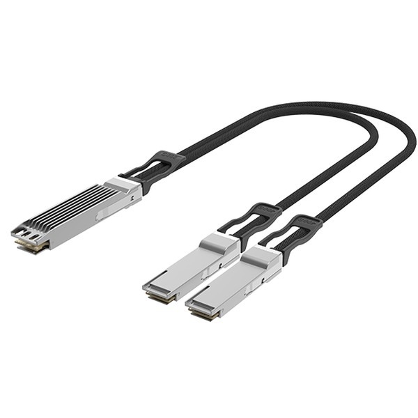
Where the leaf sits in the same rack as the nodes it serves. Passive twinax draws about 0.1 W, adds no latency, and cannot fail in a way that requires a firmware conversation. Our 800G to 2x400G breakout DAC covers the common twin-port case.
Constraint: at 100G per lane, 3 m in 26 AWG is the practical ceiling. At 200G per lane it drops to roughly 1–2 m.
2. Same row, 3–30 m: AOC
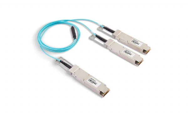
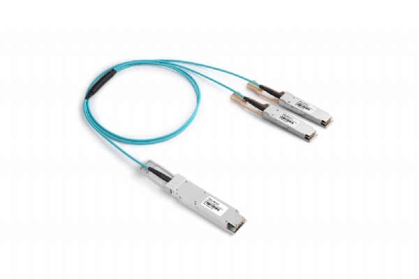
The rail-optimised middle distance, and the domain where most AI-fabric cables live. AOC gives fiber reach with plug-and-play simplicity — no separate transceivers, no connector cleaning, no polarity errors. Our 800G OSFP to 2x400G OSFP breakout AOC is built for exactly this hop.
3. Cross-hall / spine: transceivers over structured fiber
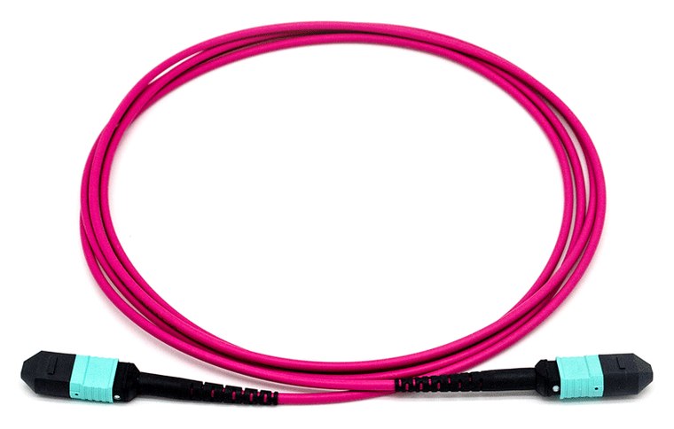
Beyond about 30 m, or any path crossing a hall boundary, use transceivers on MPO trunk fiber. Costs more per link, but the trunk outlives three generations of optics.
Reading NVIDIA Cable Part Numbers
If you are building on NVIDIA gear, the cable part numbers encode the topology. They are worth being able to read, because they tell you what a link is actually doing — and because a purchase order full of MCP7Y-somethings is otherwise impossible to review.

| Family | What it is | Where it sits |
|---|---|---|
| MCP4Y10-N### | Twin-port 2x400G OSFP to 2x400G OSFP passive DAC — straight, not split | In-rack, switch to adapter |
| MCP7Y00-N### | 800 Gb/s twin-port splitter, 2x400G OSFP to two separate 400G OSFP ends | In-rack 1:2 breakout |
| MCP7Y50-N### | 800 Gb/s twin-port to 4x200G passive splitter | In-rack 1:4 breakout |
| MFP7E10-N### | MPO-12 APC single-mode fiber trunk, factory terminated | Structured plant between racks |
| MMA4Z00-NS### | 800G twin-port SR8 multimode transceiver | Rack-to-rack over MMF |
| MMS4X00-NM / -NM-FLT | 800G 2xDR4 OSFP single-mode transceiver, finned or flat-top | Leaf to spine over SMF |
Three conventions are worth internalising:
- The numeric suffix is length. The trailing digits after the -N encode the cable length in the family's own scheme. Two part numbers differing only in those digits are the same cable at different lengths — which is exactly the field you are most likely to get wrong when re-ordering from an old PO.
- -FLT means flat-top. Flat for liquid-cooled systems and ConnectX adapter cards; the default finned/riding-heatsink variant is for air-cooled switch cages. This is the distinction that bites. Order finned-top for a liquid-cooled node and the cable is mechanically correct but thermally wrong — it fits, it links, and it runs hot for the life of the deployment.
- "Twin-port" is not the same as "splitter". A twin-port OSFP carries two independent 400G ports in one cage. Whether the far end is one connector or two is a separate question, encoded in the family prefix.
Our 800G breakout DAC and 800G OSFP112 passive DAC are built to the same twin-port conventions with programmable vendor coding, so they present correctly to Quantum and Spectrum platforms — and we can match a specific OEM part number to an equivalent build if you send us the PO line.
Gauge, Length and Bend Radius
Gauge follows length in every DAC family, NVIDIA's included: 30 AWG for roughly 1–1.5 m, 26 AWG for 2–3 m. Thicker copper carries the signal further and is also markedly harder to route.

The practical planning number: a 26 AWG 800G twinax has roughly a 6.9 mm outside diameter and wants an 80 mm bend radius. Multiply that by the forty-plus cables leaving a densely populated rack face and you can compute the volume of the cable bundle before you build it. Teams that do this arithmetic in the design phase do not end up with cable managers that physically cannot close.
Breakout Ratios in Practice
Breakout is how you avoid buying switch ports you do not need. Three ratios dominate:
- 1:2 (800G → 2x400G). The workhorse. One switch port feeds two 400G adapters. Halves your switch port count for 400G endpoints.
- 1:4 (800G → 4x200G, or 400G → 4x100G). For mixed fabrics where storage or management nodes run slower than the GPUs.
- 1:8 (400G → 8x50G). Rare in AI fabrics, common where a modern spine has to serve legacy access.
Two operational cautions. First, breakout must be configured in the switch OS — the cable alone does nothing. Second, a broken-out port usually cannot be re-aggregated without a reboot, so plan the ratio before you cable, not after.
A Worked Cable BOM for a 128-GPU Pod
Abstractions are easy to agree with and hard to order from. Here is the same design expressed as a bill of materials, for a pod of 16 nodes at 8 GPUs each — 128 GPUs, eight rails, 400G per GPU port.
| Hop | Count | Distance | Cable choice |
|---|---|---|---|
| GPU port → in-rack leaf (same rack) | 64 | 1–2 m | Passive DAC, 800G twin-port to 2x400G, 30 AWG |
| GPU port → adjacent-rack leaf | 64 | 4–12 m | 800G to 2x400G breakout AOC |
| Leaf → spine uplinks | 32 | 15–40 m | 800G DR8 transceiver pairs over MPO-16 trunk |
| Storage and management | 16 | 2–10 m | 400G to 4x100G breakout, mixed DAC/AOC |
| Trunk fiber, leaf rows to spine row | 4 runs | — | MPO-16 single-mode trunk, base-8 grouped, 20% spare fiber |
Three things fall out of writing it this way. First, the 1:2 breakout halves the switch port count on the GPU side — 128 GPU ports served by 64 switch ports. Second, only half the node-to-leaf links are actually short enough for copper, which is typical of rail-optimised layouts and always surprises teams who budgeted for all-DAC. Third, the trunk is the only line item that will still be in service in ten years, and it is the cheapest one to over-provision now.
Do this exercise before the first purchase order, in a spreadsheet, with real measured route lengths. It takes an afternoon and it routinely catches five-figure errors.
Cable Bulk Is a Thermal Problem
This is underrated until you stand in front of a fully populated rack.
Eight rails per node, 4–8 nodes per rack, plus storage and management: 40–70 cables emerging from one rack face. In 26 AWG twinax that is a physical wall directly in the intake path of the equipment behind it.
Mitigations that actually work:
- Use AOC where the distance allows it. A 3 mm AOC jacket versus a 6–8 mm twinax bundle is a large difference in blocked area.
- Break out at the switch, not the node. One thick cable to a breakout point beats eight thin ones across the aisle.
- Respect bend radius. Both for optical performance and because a forced bend is a cable that will not stay in its manager.
- Order exact lengths. Slack loops are the largest single contributor to airflow obstruction in AI racks.
Design Checklist
- Map every link to a distance regime before selecting cable types.
- Confirm finned vs flat-top for every module position — switch and adapter may differ.
- Fix breakout ratios per rail and verify the switch OS supports them.
- Specify vendor coding per platform (NVIDIA/Mellanox, Cisco, Arista) at order time.
- Over-provision trunk fiber for spine paths; under-provision nothing.
- Measure real cable routes. Nominal rack-to-rack distance is always short.
- Keep loopback modules on site for commissioning.
FAQ
Can I use standard Ethernet DAC on an InfiniBand fabric?
Physically the cable may fit, but InfiniBand link training and management differ. Use cables specified for the protocol and coded for the platform. Our DAC and AOC are programmable to the target platform at manufacture.
Why is 3 m the magic number for passive copper?
Insertion loss and crosstalk scale with length and with lane rate. At 100G/lane, 3 m in 26 AWG sits at the edge of a closed eye. Beyond that you need retimers (active DAC) or optics.
Do breakout cables reduce bandwidth?
No. A 1:2 breakout of an 800G port gives two full 400G links. The port's lanes are being grouped differently, not throttled.
How many spares should I hold?
For AOC, 2–3% of installed count. Passive DAC failure rates are lower — 1–2% is usually sufficient. Hold spares per length and per coding, not just per type.