The short answer
The real question is rarely 'which multiplexing technology is best'. It is 'I have one dark fibre pair between these two sites and I need to carry more than one thing over it — how many, and what does it cost me?' Three answers are on the shelf, separated by how tightly the channels are packed and therefore by how hard the lasers must work to stay where they belong.
CWDM gives you eighteen channels and lasers that need no cooling. DWDM gives you forty or more and lasers that must hold an optical frequency for years. MWDM sits between: twelve channels squeezed out of the low CWDM band with a small cooler, invented because Chinese mobile operators needed more 5G fronthaul lanes than CWDM offered and could not justify a DWDM line system at every cell site.
What Is CWDM?
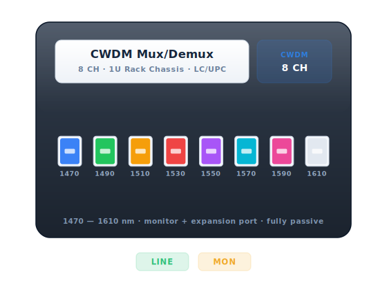
Eighteen channels on exact 20 nm steps from 1271 to 1611 nm, defined by ITU-T G.694.2. The spacing is the whole design: a passband of roughly ±6.5 nm is wide enough that an uncooled DFB laser, drifting about 0.1 nm per degree Celsius, wanders across an industrial temperature range without leaving its lane. Delete the thermoelectric cooler and you delete the largest cost and power item in a WDM transmitter. See the CWDM entry.
The catch is the water peak. Six lanes — 1351 to 1451 nm — sit on or beside the hydroxyl absorption band near 1383 nm, and on older G.652.B fibre they are useless over any distance. Only low-water-peak G.652.D flattens that peak, which is why so much installed plant runs only the eight channels from 1471 nm upward. Confirm the fibre grade first; the grid calculator lists every channel.
What Is MWDM?
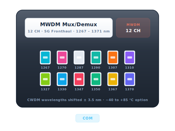
MWDM is arithmetic, not a new grid. Take the CWDM lanes from 1271 to 1371 nm and build two channels around each by shifting ±3.5 nm. Twelve come out, spanning 1267.5 to 1374.5 nm, 7 nm apart within a pair and 13 nm between pairs. It is an industry plan from Chinese operator 5G fronthaul requirements, China Mobile in particular, rather than an ITU recommendation.
Seven nanometres is too tight for an uncooled laser, so MWDM optics carry a small TEC — semi-cooled is the usual word. The job is only to stop a DFB wandering out of a band a few nanometres wide, not to hold an absolute frequency to ±0.1 nm for the module's life as DWDM must, so the cost lands far closer to CWDM. Sitting near the O-band dispersion zero, the plan is not dispersion-limited. Loss is the constraint.
What Is DWDM?
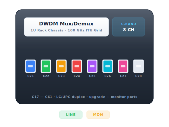
ITU-T G.694.1 defines the grid in frequency, anchored at 193.1 THz, with 100, 75 or 50 GHz spacing in normal use. Channels here are numbered f = 190.0 + n × 0.1 THz, so C34 is 193.4 THz and 1550.12 nm. The 100 GHz C-band grid runs roughly C17 (1563.86 nm) to C61 (1528.77 nm) — about forty-five channels, twice that at 50 GHz. The wavelength and frequency converter does both directions.
Holding a laser inside a 0.8 nm passband — 0.4 nm at 50 GHz — for years takes a TEC, a thermistor and usually a wavelength locker, and that is what you pay for. In return you get the one thing CWDM cannot offer at any price: every channel sits in the erbium gain band, so a single EDFA lifts all of them at once. See the DWDM entry.
CWDM vs MWDM vs DWDM: The Differences That Matter
Start from the channel count you will grow into rather than the one you need now — adding channels later means replacing the multiplexer at both ends. Then read the two rows that quietly decide most designs: insertion loss and amplification.
| CWDM | MWDM | DWDM | |
|---|---|---|---|
| Standard | ITU-T G.694.2 | Industry plan, Chinese operator 5G fronthaul | ITU-T G.694.1 |
| Channels | 18 | 12 | ~45 at 100 GHz, ~90 at 50 GHz |
| Grid | 1271–1611 nm, exact 20 nm steps | 1267.5–1374.5 nm, 7 nm in a pair, 13 nm between pairs | f = 190.0 + n × 0.1 THz; 100, 75 or 50 GHz |
| Channel passband | about ±6.5 nm | about ±2.5 nm | about ±0.11 nm at 100 GHz |
| Laser | Uncooled DFB, ~0.1 nm/°C drift | Semi-cooled DFB, small TEC | TEC-cooled DFB or tunable, held to ~±0.1 nm |
| Mux loss, each end | ~1.5 dB (4 ch), 2.5 dB (8 ch), 4 dB (18 ch) | ~3 dB (12 ch) | ~2.5 dB (8 ch) to 5–6 dB (40 ch) |
| Amplification | None — only 1531 and 1551 nm fall in the EDFA band | None — the plan is entirely O-band | EDFA lifts every channel, ~1530–1565 nm |
| Chromatic dispersion | Negligible on O-band lanes, binding at 1551 nm and above at 10G/25G | Negligible — straddles the dispersion zero | ~17 ps/(nm·km); ~1360 ps/nm over 80 km |
| Typical reach | 40–80 km at 1G, less at 10G and 25G | 10–20 km fronthaul | 80 km unamplified, thousands amplified |
| OADM and rings | Yes, passive | Rare — usually point-to-point | Yes, plus ROADM |
| Optics to stock | 18 fixed part numbers, colour-coded | 12 fixed part numbers | 40–96 fixed, or one tunable |
| Relative cost per lane | Lowest | Low | Highest |
Filter loss is the figure people forget, and it is paid twice. A four-channel CWDM mux costs around 1.5 dB, an eight-channel one around 2.5 dB and a full eighteen-channel one around 4 dB — once at the multiplexer and again at the demultiplexer. An eighteen-channel pair therefore eats roughly 8 dB before a metre of fibre is counted, and a long-reach 25G CWDM SFP28 has perhaps 18 dB to spend. Twelve-channel MWDM is about 3 dB a side, a forty-channel DWDM mux 5 to 6. Put the real numbers into the link budget calculator rather than assuming the fibre dominates — on a metro span it usually does not.
Amplification is the hard wall between the grids. Erbium has gain from roughly 1530 to 1565 nm, a window about 35 nm wide; the CWDM grid spans 340 nm, and exactly two of its channels — 1531 and 1551 nm — fall inside it. You can amplify those two lanes, but you cannot amplify a CWDM system. DWDM was placed in the C-band precisely so one amplifier serves every channel, which is why long-haul WDM is dense and not coarse. If the span needs gain, the grid decision is already made; the pluggable EDFA guide covers the port-sized units.
Dispersion binds differently on each grid. Chromatic dispersion on G.652 is near zero around 1310 nm and about 17 ps/(nm·km) at 1550, so the low CWDM lanes and all of MWDM are effectively dispersion-free while 1551 nm and above accumulate roughly 1360 ps/nm over 80 km. A 10G part usually tolerates that; a 25G one on the same fibre usually does not, which is why 10G reaches further than 25G on identical glass. Check your longest lane in the dispersion calculator before assuming a working 10G plan survives a move to 25G.
Which One Should You Choose?
An enterprise or campus dark-fibre pair: CWDM
For fewer than eight or ten services between two buildings this is the right default and it is not close. Uncooled optics, a passive box mux at each end, no power feed and nothing to configure. Buy the eight- or sixteen-channel unit even if you light four lanes today, because outgrowing the mux means replacing both ends. Confirm the fibre is G.652.D before specifying anything between 1351 and 1451 nm, and label the ports — CWDM colour codes are not universal between vendors.
5G fronthaul from a cell site: MWDM
Twelve semi-cooled lanes on one pair is exactly the problem MWDM was built for: many 25G links back from radios over fibre already in the ground that cannot be added to cheaply. Eighteen CWDM channels sounds like plenty until you notice the reliably usable ones on legacy plant are the low O-band group. MWDM doubles those without putting wavelength lockers and a forty-part-number stocking problem in a base station. Specify industrial temperature rating for a street cabinet, and read DDM after the first hot afternoon. Where a site needs more than twelve O-band lanes, an O-band DWDM plan on an 800 GHz grid is the next step.
Metro data centre interconnect: DWDM, and probably coherent
Carrying tens of services, or anything at 100G and above between sites, DWDM is the only grid that scales. At 10G and 25G, fixed or tunable DWDM optics into a 100 GHz mux is a well-worn design, and tunables collapse the stocking problem to one part number. At 400G the answer changes shape: a coherent pluggable drives the DWDM line straight out of a router port and corrects dispersion in the DSP — 2400 ps/nm as standard on 400ZR. See 400ZR vs ZR+ vs transponder and the OpenZR+ DCI guide. It replaces the transponder, not the mux or the amplifier.
Long-haul and subsea-adjacent: DWDM, and it stops being a filter question
Past metro distances the design is no longer 'which multiplexer' but 'how does the OSNR budget close'. Every EDFA adds noise roughly equal to its noise figure and each doubling of the span count costs a further 3 dB, so an amplified system runs out of signal-to-noise rather than power — adding gain at the end amplifies the accumulated noise too. CWDM and MWDM are not in this conversation: neither can be amplified, and both exhaust their budget in the first hundred kilometres. Here the channels are coherent, the spacing may be 75 GHz or flexible, and the line system wants modelling end to end before anything is bought.
A ring rather than a point-to-point link: count nodes, not kilometres
An OADM at each site turns a WDM link into a network: drop what terminates here, add what originates here, express the rest untouched. Budget roughly 1.5 dB a node with its connector pairs, and note that it accumulates — eight nodes is 12 dB before any fibre. Crosstalk accumulates too: leakage from every upstream node adds while the wanted signal loses 1.5 dB a hop, which is the mechanism behind a ring that works on a short chord and errors the long way round at a healthy receive power. Both CWDM and DWDM OADMs are passive glass; a ROADM buys remote re-routing at several times the cost.
Frequently Asked Questions
How many services can I get down one dark fibre pair?
Eighteen with CWDM on low-water-peak G.652.D, eight to ten if the fibre is older; twelve with MWDM; about forty-five on a 100 GHz DWDM grid and ninety at 50 GHz. Those are channel counts, not service counts — each channel carries whatever its transceiver carries, so one DWDM channel can be 400G. The practical ceiling is usually the loss budget rather than the grid, so price the filters in the link budget calculator first.
Can I mix CWDM and DWDM on the same fibre?
Yes, and it is a common way to grow. The whole C-band sits inside the CWDM 1551 nm channel, so a filter can hand that lane to a DWDM mux while the other CWDM lanes carry on. It costs an extra pair of filters and their insertion loss at each end. Send us the existing channel plan and we will work out what fits.
Why can CWDM not be amplified?
Because the grid is far wider than the amplifier. An EDFA has gain over roughly 1530 to 1565 nm; CWDM spans 1271 to 1611 nm. Only the 1531 and 1551 nm lanes fall inside, so you can amplify two channels out of eighteen — which is not a system. Once fibre loss has eaten the budget, a CWDM link simply ends.
Is MWDM the same as LWDM or LAN-WDM?
No, though they are constantly confused. LAN-WDM is the tight four-lane O-band plan at 1295.56, 1300.05, 1304.58 and 1309.14 nm — 800 GHz apart — carried inside LR4 and ER4 transceivers. MWDM is a twelve-channel fronthaul plan derived by shifting the low CWDM lanes ±3.5 nm. Both live in the O-band and both need some cooling, but the grids and the applications differ and neither interoperates with the other.
Does the multiplexer care what speed I run?
Not directly — it is passive glass that filters wavelengths, not bits. What changes with speed is the optic at each end. A CWDM plan comfortable at 1G and 10G can fail at 25G on the long lanes for two reasons at once: less budget to spend on your filters, and far less dispersion tolerance above 1550 nm. Check both before reusing an existing mux at a higher rate.
When does coherent change the answer entirely?
At 100G and above over metro and longer spans. A coherent receiver recovers amplitude and phase, so dispersion is undone mathematically and the limit becomes OSNR. That makes 80 to 120 km routine from a router port with 400ZR, and it makes the coarse grids irrelevant at those rates — there is no coherent CWDM. Inside a campus at 10G or 25G it is expensive overkill and CWDM is still the right answer.
The Parts We Build
We build the passive filters and the optics that ride on them — every plan on this page, tested channel by channel before dispatch.