DAC Cables: AWG, Length Limits and When to Go Active
A direct attach copper cable is the least glamorous item in a data centre and the one most likely to be ordered from memory. Somebody has a spreadsheet of lengths from the last build, the ports look the same, and three metres worked fine last time.
Then the fabric runs at twice the lane rate and half the cables will not link. Nothing is faulty. The copper channel simply ran out of budget, and it did so at a distance that has halved twice since the spreadsheet was written.
This is the engineering behind that: what gauge does, why reach collapses with lane rate, where retimed and optical assemblies take over, and how to choose lengths that actually dress into a rack instead of hanging in loops behind the door.
What AWG Actually Buys You
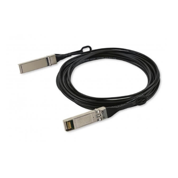
A DAC is a pair of shielded twinaxial conductors per lane, with a connector moulded on each end and an EEPROM inside the plug that tells the host what it is. There is no signal processing in a passive assembly. Everything the transmitter sends arrives attenuated and smeared, and the receiver's equaliser has to make sense of it.
Wire gauge sets how much attenuation. Thicker copper — a lower AWG number — has lower resistance and lower insertion loss per metre, so it carries further. It is also stiffer, thicker, heavier and has a larger minimum bend radius.

The weight and airflow cost is real and gets underestimated. A 32-port switch cabled entirely with 24 AWG assemblies has several kilograms of copper hanging off the faceplate, and a bundle stiff enough to hold whatever shape it was forced into. That bundle sits directly in the exhaust path of the switch and the intake path of whatever is above it. In a thermally tight rack, moving from 24 AWG to 28 AWG on the short hops is a measurable airflow improvement before it is anything else — on top of the roughly 30 W per link that choosing copper over optics already saved, which the power and thermal calculator quantifies for your own rack.
Why the Cable That Worked at 25G Fails at 50G
Copper attenuation rises with frequency. Double the symbol rate and the loss at the frequencies that matter roughly doubles too, so the same cable presents a channel that is twice as difficult. On top of that, the move from NRZ to PAM4 packs four amplitude levels into the same voltage swing, which costs about 9.5 dB of signal-to-noise ratio before any cable is attached.
The result is that the standardised passive reach has halved at every generation, and the IEEE objectives track it exactly.

| Per-lane rate | Modulation | IEEE project | Passive reach objective | Typical port |
|---|---|---|---|---|
| 25 Gb/s | NRZ | 802.3bj / 802.3by | at least 5 m | 25G SFP28, 100G QSFP28 |
| 50 Gb/s | PAM4 | 802.3cd | at least 3 m | 50G SFP56, 200G QSFP56, 400G QSFP-DD |
| 100 Gb/s | PAM4 | 802.3ck | at least 2 m | 400G QSFP112 / OSFP, 800G OSFP |
| 200 Gb/s | PAM4 | 802.3dj | at least 1 m | 800G OSFP224, 1.6T OSFP224 |
So the five-metre 25G SFP28 DAC that has worked reliably for six years is not defective when the same run at 50G per lane will not come up. It is a channel with roughly twice the loss being asked to carry a signal with 9.5 dB less margin. The physics has not changed; the demand has.
Two important qualifications. First, these are objectives, not maxima — they define the distance the standard guarantees to work with a compliant host at both ends. Vendors ship longer passive assemblies and they often link, because a particular host board is shorter or lower-loss than the worst case the standard assumes. Second, that is exactly why they sometimes do not: the same cable in a different chassis sees a different host channel and fails. A passive cable beyond the objective reach is a link that works until you move it.
Passive, Active, AEC and AOC
Four assembly types, in increasing order of what is inside them.
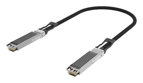
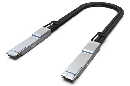
Passive DAC. Copper only. No power beyond the EEPROM, no added latency, nothing to fail in firmware. An 800G OSFP passive DAC is the correct answer whenever the distance allows it, and increasingly that means inside one rack.
Active DAC (ACC). Copper with an equaliser or amplifier in each plug. Extends reach modestly — typically by half again to double — and draws a couple of watts. Useful at 25G and 50G per lane, largely bypassed at 100G and above in favour of retimed assemblies.
AEC — active electrical cable, retimed. A full retimer in each plug that recovers the clock, cleans the signal and transmits it again. Because each half of the link is a fresh signal, an AEC does not care about the total channel the way a passive cable does. Commercial 800G AECs run to roughly 5 to 7 m in 30 to 32 AWG — far thinner than the passive cable they replace, which is a substantial part of the appeal. The cost is a few watts per end, latency in the retimer, and firmware that can be wrong.
AOC. Fibre with permanently attached optics at both ends. Reaches tens of metres, costs the power of two transceivers, and has no end faces to clean, so none of the insertion loss bookkeeping of a patched channel applies. Where cable bulk and airflow dominate, it wins on physical grounds before it wins on distance. The DAC, AOC and ACC comparison sets the three side by side, and the cost-per-port framework puts numbers on the trade.
The practical shape of this at 200G per lane is worth stating plainly: passive copper becomes an in-rack-only technology. With a one-metre objective, the passive DAC serves the top-of-rack hop and nothing else, and everything from adjacent-rack upwards moves to AEC or optics. If you are designing a 1.6T generation fabric on the assumption that three-metre copper will still be available, the design needs revisiting.
The FEC Dependency Nobody Mentions
Every one of these reach numbers assumes forward error correction is running. At 50G per lane and above, KP4 — RS(544,514) — is not optional, and the specified pre-FEC bit error rate threshold of 2.4e-4 is what makes a lossy copper channel usable at all. A raw error rate that would be catastrophic uncorrected is normal on a DAC.
Three things follow that matter in the field.
A marginal DAC does not fail cleanly. It links, passes traffic, and sits close to the correction limit. Post-FEC the link looks perfect. Trend pre-FEC BER per port and a cable that is too long, too tightly bent or slightly crushed shows up weeks before it drops a frame. There is no DDM optical power to fall back on here — on copper, pre-FEC BER is the only health signal you get.
FEC must match at both ends. On DAC links this is the most common configuration fault by a wide margin, because some platforms auto-negotiate FEC over copper and some do not, and the module's EEPROM length field influences what the host chooses. Two ends that disagree produce a link that comes up and errors continuously.
Auto-negotiation and link training exist on copper and can go wrong. Unlike an optical link, a DAC negotiates and trains its equalisers with the far end. A mismatch in what the two hosts will negotiate produces a port that cycles up and down. Forcing speed and FEC identically at both ends resolves most of these.
Breakout DACs
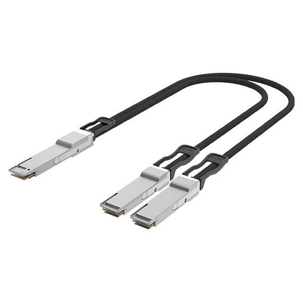
A breakout DAC is one parent plug and two, four or eight child plugs on a common jacket — an 800G to 2×400G assembly, or the 400G QSFP-DD family split to 4×100G. Inside a rack it is the cheapest link money can buy, and it removes eight optics from the power budget.
Three cautions specific to breakout copper. The reach limit applies to the whole assembly, parent plug to child plug, so a 2×400G breakout at 100G per lane is subject to the same roughly two-metre budget as a straight cable — and the fan-out point consumes part of the physical run. Second, a breakout assembly is one SKU per length and per ratio and per coding, which multiplies the spares matrix faster than anything else in the catalogue. Third, the switch still has to be configured for the ratio before the cable will do anything; the breakout configurator produces the matching parts list, and the breakout guide covers the port-group constraints that decide whether the ratio is available at all.
Planning Lengths From the Rack Elevation
Most DAC length problems are not reach problems. They are dressing problems, caused by choosing lengths from a catalogue instead of from a drawing.
Measure the route, not the gap. A server 12U below the switch is not 0.5 m away. The cable leaves the faceplate, turns into a vertical manager with a bend that respects the minimum radius, runs down, turns back out and enters the port — commonly 1.5 to 2 m for a hop that looks like half a metre on the elevation.
Standardise on three lengths, not seven. One length for the upper third of the rack, one for the middle and one for the bottom covers almost everything. Fewer SKUs, fewer wrong cables in the box, and an installer working from a rule rather than a list.
Round up by one step, never two. A cable 0.5 m too long dresses into the manager and disappears. A cable 1.5 m too long becomes a coil, and a coil of stiff twinax blocks airflow, prevents the door closing and makes every subsequent cable harder to route. Excess length is not free storage.
Treat a hop that needs the full objective reach as a warning. It will work today and become the first thing to fail when the rack is re-arranged or the fabric moves a lane rate.
Check the bend radius against the cable manager, not the datasheet. A 24 AWG assembly with a 38 mm minimum radius does not turn inside a 1U horizontal manager. This is a physical incompatibility that no amount of cable ties fixes, and it is discovered on installation day unless somebody checks the drawing.
We build DAC, ACC, AEC and AOC assemblies in Shenzhen to the length, gauge and ratio you specify rather than to a fixed catalogue, with both ends coded to the exact switch platform and software release on the order — which on copper matters more than people expect, because the length and FEC hints in the EEPROM influence what the host negotiates. Every assembly is tested end to end at rate before dispatch, and for a build we will work from your rack elevation and return the length schedule, so the box that arrives on site contains cables that dress rather than cables that fit.
FAQ
Can I use a longer passive DAC than the standard says? Sometimes, and it is a risk you take knowingly. Longer assemblies work where the host boards at both ends are better than worst case. The same cable moved to a different chassis may not link, so treat over-length passive cable as unsupported inventory rather than as stock.
Does a thicker gauge improve a link that already works? No. A link either closes with margin or it does not. If you have margin, use the thinner cable and get the airflow and manageability back.
Is an AEC just an expensive DAC? No — it retimes, so the two halves of the channel are independent. That is why a 30 AWG AEC reaches further than a 24 AWG passive cable while being far thinner. It costs a few watts per end and adds latency in the retimer.
Why does my DAC link but show errors? Check FEC configuration at both ends first, then pre-FEC BER, then the physical cable for a crush or a bend inside the minimum radius. Copper faults are usually mechanical and usually visible if you follow the cable.
Do DAC cables need vendor coding? Yes, exactly as transceivers do. The host reads an EEPROM in the plug and decides whether to accept the assembly and what length and FEC behaviour to assume. A cable between two different platforms needs each end coded for its own switch.
What length should I standardise on for a 1.6T build? With a one-metre passive objective at 200G per lane, plan passive copper for the in-rack hop only and budget AEC or AOC for anything that crosses a cabinet boundary. Designing on three-metre copper at that lane rate will not survive contact with the rack.