Fibre Test Kit Essentials: VFL, Power Meter, OTDR, Loopback
A fibre test kit is a set of instruments that each answer one narrow question very well and every other question badly. The expensive field mistakes are almost never a faulty instrument; they are reaching for the wrong one, or trusting a number it was never measuring.
An OTDR does not measure the loss of a short data centre channel, and using it as though it does gives a confident number that is wrong. A power meter says a channel is bad and refuses to say where. A loopback proves the transceiver works and says nothing about the fibre. A visual fault locator finds a break on a patch cord in ninety seconds and nothing four kilometres down a single-mode span. This is what each really measures, what it misses, and the order to use them in.
The Order to Reach for Them
Both jobs work from the ends inwards, with the cheapest tool first.

For a link that is down, that sequence resolves most faults before anyone opens the OTDR case. Reading DDM at both ends costs nothing and separates three cases: no transmit power is a module or host problem, healthy transmit with no receive is the fibre or a connector, and low-but-present receive is loss in the channel. Only the last needs a loss measurement.
For acceptance the order differs, because you are proving rather than finding: inspect and clean every end face, take Tier 1 insertion-loss measurements on every fibre against a recorded reference, then Tier 2 traces where the spans are long enough for an OTDR to mean anything. Keep both — Tier 1 is what the design was budgeted against, the trace is what tells you three years later what changed.
The step everyone skips is the second. Contamination is the largest single cause of optical faults, and the only one testing itself can introduce, which is why inspection and cleaning discipline matters more than any instrument in the bag.
The Visual Fault Locator, and Where It Stops
A VFL is a red laser, typically 650 nm, launched into the fibre so faults leak visible light. It answers three questions quickly and none numerically: is this fibre continuous, which of these twelve is which, and is there a break or sharp bend visible through the jacket. No far-end technician, no reference, no configuration. The limits matter more than the capability.
The range is far shorter than the box claims. At 650 nm, single-mode fibre attenuates in the region of 5 to 7 dB per kilometre, roughly twenty times the loss at 1310 nm. Realistic limits are four to five kilometres for continuity through a sharp bend, six or seven for spotting a break in good conditions. Claims of 20 or 50 km describe the laser, not the job.
Jacket colour and ambient light decide whether you see anything, since some pigments absorb red almost completely. Shade the cable with a hand before concluding a fibre is broken. And it measures nothing: a visibly acceptable fibre can still be well outside its insertion loss budget. Never point one at a live port or an eye.
Light Source and Power Meter: Tier 1 Done Properly
A calibrated light source at one end and a power meter at the other is the reference measurement for a fibre channel. It is Tier 1 testing, it is what the cabling standards require, and it produces the number the design was budgeted against: total insertion loss in dB, per fibre, per wavelength.
It is also the instrument most often used incorrectly, and the reason is the reference. You connect source to meter through test cords and record that power as 0 dB; whatever is in the reference is excluded from the result — a choice that moves the answer by as much as the whole budget of a short channel.
| Reference method | Old name | Cords in reference | Connector pairs measured | Use when |
|---|---|---|---|---|
| One-jumper | Method B | 1 | Both ends | Patch panel to patch panel — the standard case |
| Two-jumper | Method A | 2 | One end only | An equipment cord is part of the link |
| Three-jumper | Method C | 3 | Neither end | Fibre only, and MPO trunk-to-trunk |
ANSI/TIA-526-14 renamed these in 2010, but both vocabularies remain in daily use. The naming is not the point: a one-jumper reference includes both connector pairs and a three-jumper reference includes neither, and on a 100 m OM4 channel that difference is most of the measured loss. Record the method on the result — unnamed, the numbers are comparable to nothing.
Multimode has a second trap: the launch condition. How light is distributed across the core changes how much survives a connector, so the same channel gives different answers under an overfilled and an underfilled launch. Encircled flux is the standardised fix — a defined power distribution across the core radius that every compliant source must produce. ANSI/TIA-526-14-C requires it at 850 nm on 50/125 fibre; IEC 61280-4-1 requires it at 850 and 1300 nm on all multimode types. Published work puts the uncertainty from an uncontrolled launch as high as about 40%, which is why it replaced the older coupled-power-ratio and mandrel-wrap approaches. Single-mode has no such problem — a small, real advantage of OS2 plant.
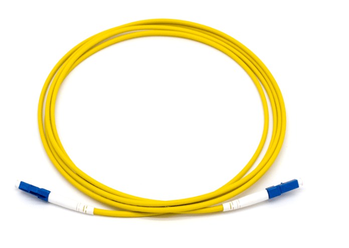
Two habits. Use dedicated reference jumpers, inspected before every reference; a scratched one silently adds loss to every result after it. And compare the measurement against the design budget rather than a rule of thumb — the link budget calculator builds the expected number, and the dB to percentage converter turns dB into the share of light lost.
OTDR: What Tier 2 Adds and What It Hides
An OTDR launches a pulse and plots what comes back — backscatter along the fibre, reflections at connectors and breaks. From one end, with no far-end equipment, it produces a map: where each event is and what each costs. That is why Tier 2 exists, and it is unbeatable at locating a break by distance along an outside-plant span. What it is bad at, and why it is the last tool in the sequence:
Dead zones. After each reflective event the receiver is saturated and resolves nothing for a short distance. The event dead zone — the minimum separation at which two reflective events can be told apart — is around a metre on a good single-mode instrument and tens of centimetres on a multimode one. The attenuation dead zone, before a non-reflective event such as a splice can be measured at all, is always longer. In a data centre where the channel is 30 m with four connectors, most events fall inside each other's dead zones and the trace is uninterpretable.
It infers loss rather than measuring it. An OTDR reads backscatter in one direction, and at a joint between fibres with different backscatter coefficients it can display a gainer, an event that appears to add light. Hence bidirectional averaging on splice acceptance.
It needs launch and receive fibres. Without a launch cord the first connector sits inside the instrument's own dead zone and is not measured; without a receive cord neither is the last. A connector loss reported as "0.0 dB" usually means they were missing.
Loopbacks: Proving the Module, Not the Plant
A loopback returns a transceiver's transmit light to its own receiver. The port comes up against itself and errors can be counted. It answers one question: is the fault inside the switch, or outside it?
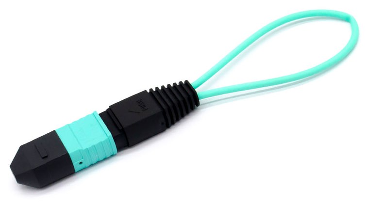
A clean loopback proves the transmitter and receiver work, the cage and host port are sound, and the module is recognised and coded correctly — many causes eliminated in two minutes with a component that costs almost nothing. It proves nothing about the plant, and a module that loops back perfectly but will not link across the room has told you exactly what you wanted to know. For duplex modules a loopback is an LC pair with transmit joined to receive; for parallel modules the map is what people get wrong.

An MPO-12 transceiver uses positions 1 to 4 for transmit, leaves 5 to 8 dark, and uses 9 to 12 for receive. A correct MPO-12 loopback joins 1 to 12, 2 to 11, 3 to 10 and 4 to 9, leaving 5 to 8 unconnected: each transmit lane returns on a receive position, mirrored about the centre of the ferrule. An ordinary MPO patch cord maps 1 to 1 and puts transmit into transmit, so the module hears nothing and the port stays down — regularly misread as a dead module.
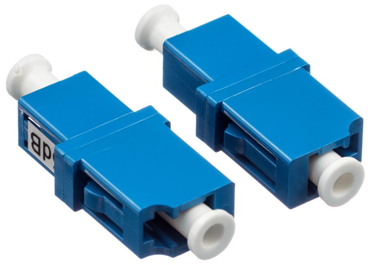
Two cautions. Polish must match: a single-mode parallel module wants an APC loopback and a multimode one flat polish, and mating the two costs well over a decibel, ruins the return loss and scratches both ferrules, as the APC and UPC comparison explains. And a long-reach module will overload its own receiver, since an LR4, ER4 or ZR4 launching at rated power into itself is far above saturation and the errors that follow read as a failed module. Fit a fixed attenuator sized to bring the return inside range — 5 dB for a 10 km part, 15 to 20 dB for the amplified classes — using the optical power converter to size it.
The Probe, and What to Own at Each Budget
The video inspection probe pays for itself fastest and is bought last. It magnifies an end face onto a screen so you can see the contamination a loss measurement can only infer, and modern probes grade the image against IEC 61300-3-35 zone criteria, which removes the argument about whether a particular speck matters.
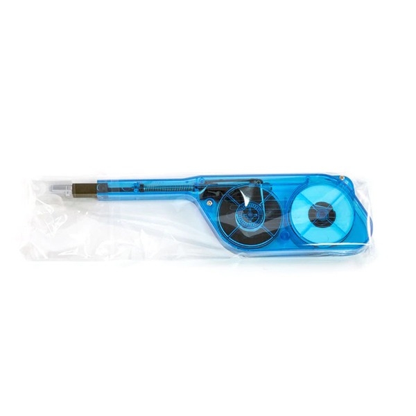
Two things make it indispensable. It inspects bulkhead end faces — the side of a mated pair you cannot see and usually the dirty one. And it separates contamination, which cleans off, from damage, which does not. End-face inspection before every mate is the highest-yield habit in fibre work; an MPO cleaner and inspection kit covers both for multi-fibre ferrules.
Under a few hundred: inspection probe, click cleaners for LC and MPO, a pen-style VFL, and a loopback for each form factor in your estate. That set finds contamination, breaks and dead modules. Buy the probe first even if it means buying nothing else.
A working budget: add a dual-wavelength source and power meter with an encircled-flux-compliant multimode launch, reference jumpers in the polishes your plant uses, and fixed attenuators. You can now certify to Tier 1. A media converter earns its place here if you support mixed copper and fibre edges, because it lets one person confirm a link end to end.
Full capability: an OTDR with the pulse-width range your spans need, launch and receive fibres, and an MPO-capable meter so trunks are tested per fibre.
We measure every assembly we build fibre by fibre before it ships — insertion loss and return loss per fibre, per serial number, polarity verified rather than assumed — and the results travel with the cable, so the trunk arrives with its Tier 1 record already made. We build the loopbacks, attenuators, reference jumpers and cleaning tools in the same factory. Tell us the form factors and reaches in your estate and we will say which loopbacks and attenuator values you need; our incoming QC checklist covers what to test on arrival.
FAQ
Do I need an OTDR for a data centre? Usually not. Channels are short, dead zones swallow the events, and Tier 1 with a source and meter is required and sufficient. Own a probe and a meter first; hire an OTDR for inter-building spans.
Why do two contractors get different loss numbers on the same fibre? Almost always the reference method, sometimes the launch condition. Insist that every result names both.
Can I use a normal MPO patch cord as a loopback? No. It maps position 1 to position 1, connecting transmit to transmit. A loopback reverses the map so each transmit lane lands on a receive position. The two look identical in a photograph.
My module loops back cleanly but the link is still down. The transceiver, cage and host port are good, so the fault is in the plant or at the far end. Inspect every end face, check receive power at the far end, and confirm polarity through any harness or cassette — the full diagnostic sequence sets out the rest.
How often should reference cords be replaced? Inspect before every reference and replace on evidence rather than on a calendar, but treat them as consumables. A cord mated a few hundred times is a different component from the one you bought.