Uniboot, Mini-Boot and VSFF: The High-Density Connector Guide (LC, SN, MDC, CS)
Nobody specifies a patch cord by its boot. Then a 1U panel arrives with 48 duplex ports, the cords go in, the cable manager will not close, and the boot becomes the most important thing about the cord.
This is a guide to the mechanical end of high-density fiber: the boot styles that decide how many cords fit and how fast you can change one, and the very-small-form-factor connectors that are quietly replacing LC at the top of the density curve.
Why the Boot Became a Design Decision
An LC connector's optical performance comes from a 1.25 mm ceramic ferrule and its polish. That part is settled engineering — a good LC patch cord delivers ≤0.3 dB insertion loss whatever plastic surrounds it.
What the surrounding plastic decides is everything else: how much depth the cord needs behind the faceplate, how tightly cords pack side by side, whether you can grip one to remove it from a full panel, and how much force the fiber sees when someone bends the bundle to close a door.
As port density rose from 24 to 48 to 72 duplex positions per rack unit, those mechanical questions stopped being cosmetic. A cord that needs 45 mm of straight depth behind the panel is unusable in a cabinet with 40 mm of clearance, regardless of its insertion loss.
The Four LC Boot Styles

Standard duplex
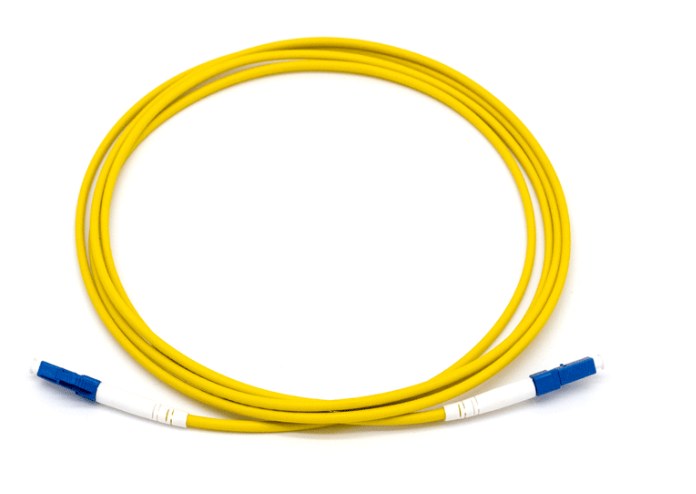
Two simplex LC connectors held together by a plastic clip, each with its own round cable and its own boot. The oldest and cheapest arrangement, and still perfectly good in low-density panels. Its weaknesses appear in bulk: two cables per duplex link means twice the bundle volume, and changing polarity means unclipping the two connectors and physically swapping them.
Uniboot
One round cable containing both fibers, one connector body, one boot. The bundle volume drops by roughly half for the same number of links — which in a full rack is the difference between a manageable cable path and a wall.
The second advantage is polarity: on a proper uniboot design, you reverse polarity by manipulating the boot, without tools and without breaking the connector down. On a standard duplex cord the same operation means unclipping, swapping and re-clipping — fiddly at the best of times, and genuinely difficult inside a live panel.
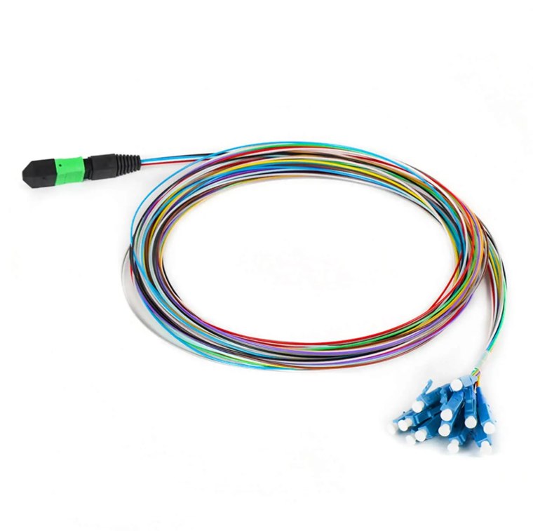
Our MTP/MPO-to-LC uniboot harnesses use this style for exactly this reason: breakout harnesses are where polarity mistakes are most likely and where access is worst.
Uniboot with push-pull tab
A uniboot cord with a rigid tab extending back from the connector. You insert and extract by pulling the tab rather than by pinching the latch, which is the only practical way to remove a cord from the middle of a fully populated high-density panel.
If you have ever tried to get two fingers onto an LC latch surrounded by 47 other cords, you already understand why this exists.
Mini-boot / short boot
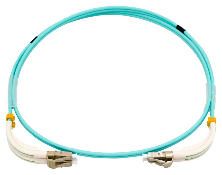
A shortened strain-relief boot, typically saving 15–20 mm of depth behind the faceplate. Frequently combined with uniboot construction and with an angled exit.
Uniboot Polarity Reversal, Step by Step
This is the feature people buy uniboot for and then never use, usually because nobody showed them how. The mechanism varies slightly by manufacturer, but the sequence is consistent:
- Release the boot. On most designs the boot slides back or a small clip disengages, freeing the connector body from the cable's rotational lock.
- Rotate the two connector bodies 180° relative to the cable. The A and B positions exchange.
- Re-seat the boot. The lock re-engages and the cord is now the opposite polarity.
Total time: about ten seconds, no tools, no interruption to the fiber itself. Compare that with sourcing a different cord, and it becomes clear why uniboot dominates in environments where polarity is discovered rather than designed.
Two cautions. First, not every cord marketed as uniboot supports field reversal — some are simply single-jacket construction with a fixed polarity. Ask explicitly. Second, reversal changes the cord, not the documentation; update your records or you will spend the reversal savings on troubleshooting later. Our polarity guide covers how the cord-level convention fits into a whole-channel scheme.
Mini-Boot and the Closing Door
Mini-boot is the least glamorous item on this list and the one that most often rescues a build.
The arithmetic is simple. A standard LC boot needs roughly 40–50 mm of straight cable behind the connector before the fiber can bend. In a 600 mm deep cabinet with equipment at the front and a door at the back, that depth may not exist. The usual field response is to force the bend, which puts the fiber past its minimum bend radius and produces exactly the kind of intermittent, temperature-dependent loss that takes three site visits to find.
A mini-boot cord, especially in a 45° or 90° angled exit variant like our angled-boot LC duplex cords, lets the cable turn immediately. The door closes, the bend radius is respected, and the link is stable.
Specify mini-boot or angled-boot when any of these are true: the cabinet is shallower than 800 mm, the panel is above 24 duplex ports per RU, or there is a rear door that has to close over the cable path.
VSFF: SN, MDC and CS
Boot engineering can only take LC so far. At some point the 1.25 mm ferrule pitch itself is the limit, and that is where very small form factor connectors come in.

SN, developed by Senko, uses 1.25 mm ferrules in a very narrow duplex body with a sliding latch. It was designed with transceiver breakout in mind: a 400G or 800G module with multiple duplex ports on its face needs connectors far narrower than LC to fit at all.
MDC, from US Conec, targets the same problem with a push-pull boot mechanism. The design intent is that a single finger can insert or extract a connector in a densely packed field — the same problem the push-pull tab solves for LC, addressed natively.
CS, also from Senko, sits between LC and the ultra-dense pair. A wider pitch than SN or MDC, roughly double LC density, and adopted primarily on 400G duplex transceiver ports where the module face has room for something larger than SN but not for LC.
What the Density Actually Buys

The honest framing: boot optimisation buys you roughly 50% more density within LC. Moving to VSFF buys you 2–3x. If your problem is that a panel is 20% too full, a uniboot mini-boot cord solves it. If your problem is that you need to triple the fiber count in the same rack, no boot will save you and it is time to look at SN or MDC.
Balanced against that, three real costs of going VSFF:
- Ecosystem depth. LC is universal. VSFF adapters, cassettes, cleaning tools and test leads are available but the choice is narrower and lead times are longer.
- Test and inspection tooling. Your existing LC inspection tips and reference cords do not fit. Budget for new ones per connector family.
- Serviceability at density. A panel packed to 288 fibers is only useful if a technician can still change one cord in it. Leave working clearance; density you cannot service is not density.
Choosing Without Painting Yourself Into a Corner
- Start from the cabinet, not the catalogue. Measure the depth behind the panel and the door clearance. That number eliminates half the options immediately.
- Default to uniboot for anything you will re-patch. The polarity flexibility and halved bundle volume cost very little and pay back on the first change.
- Add mini-boot or an angled exit wherever a door closes over the cords.
- Use push-pull tabs above 24 duplex ports per RU. Below that, standard latches are fine.
- Only go VSFF for a real density requirement — usually transceiver-face breakout, or a genuine 2x+ fiber-count increase in fixed space.
- If you go VSFF, pick one family and document it. Mixed SN and MDC plant is the single most expensive mistake available in this whole category.
- Keep the ferrule and polish decisions separate. Boot and body are mechanical; UPC versus APC is optical and follows the rules in our polish guide.
FAQ
Does a uniboot cord have worse insertion loss than a standard duplex cord?
No. The ferrule, polish and fiber are the same. Any difference between two cords comes from manufacturing quality, not from boot style.
Can I reverse polarity on any uniboot cord?
Only on designs that specifically support field reversal. Some single-jacket cords are marketed as uniboot but have a fixed polarity. Confirm before ordering if you need the feature.
Is MDC compatible with SN?
No. Different bodies, different latches, no adapter between them. Standardise on one per site and use hybrid jumpers at the boundary with LC plant.
Do VSFF connectors need different cleaning tools?
Yes. Both the cleaning tips and the inspection scope adapters are family-specific. Order them with the first cords, not after the first contamination problem.
Should I replace my LC plant with VSFF?
Almost certainly not as a wholesale programme. VSFF earns its place in specific high-density positions — transceiver breakout and packed patch fields. LC remains the right default everywhere else.