Finned vs Flat-Top OSFP: Getting 800G Heat Out of the Cage
For twenty years the top of a transceiver was a piece of sheet metal that nobody specified. You ordered a module by reach and coding, it arrived, it went in the cage. At 800G that stopped being true, for reasons of arithmetic rather than fashion: a module dissipating seventeen watts inside a body the size of a stick of chewing gum has to hand that heat to something, and there are only two things it can hand it to.
Either the module carries its own fin stack and gives the heat to air moving across it, or the module is flat on top and gives it by conduction to a heatsink belonging to the switch. Those are the two products. They share an optical specification, a coding option and most of a part number — and in the MSA-defined case they are keyed so that one will not enter the other's cage. Getting it wrong is expensive because it is not discovered on a spreadsheet. It is discovered in a rack, at night, by someone holding a module that will not seat.
Why the Lid Became a Design Decision
Follow the watts. A 100G QSFP28 short-reach module draws about 3.5 W. A 400G OSFP short-reach module draws around 12 W. An 800G module with eight PAM4 lanes and a full DSP draws 14 to 17 W, and a 1.6T module reaches 30 W. Over three generations the power per port has grown roughly ninefold; the faceplate has not grown at all. A 1U switch still presents 32 cages across nineteen inches, and the air available to cool them is whatever fits between the cage rows.
Inside the module the thermal path is short and unforgiving. Heat leaves the laser and the DSP die, crosses a substrate and a thermal interface, reaches the shell, and then has to get from the shell to somewhere else. Every interface has a resistance, and the last is the one the lid decides. OSFP was drawn with a larger body than QSFP-DD for exactly this reason — the argument is in our 800G form-factor article — and the consequence here is narrow: OSFP got the option of putting the heatsink on the module, and QSFP-DD never had it.
The Two Cooling Paths
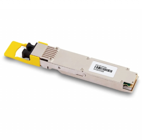
Path one: the fin stack belongs to the module. This is the classic OSFP. The lid is a finned aluminium extrusion, the cage is a plain sheet-metal shroud with no heatsink of its own, and chassis air flows directly over the module's fins. The module occupies roughly 13 mm inside the cage, and every watt leaves through metal it brought with it — so the module vendor owns the thermal design.
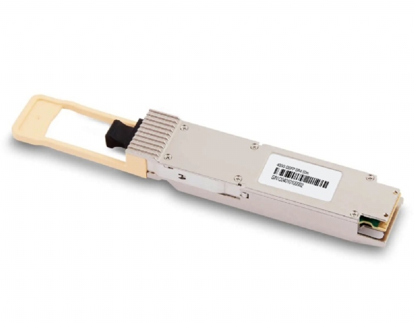
Path two: the fin stack belongs to the host. The module presents a flat metal top, the cage carries a spring-loaded riding heatsink pressing onto that surface, and heat crosses the joint by conduction before it ever meets air. This is how QSFP-DD has always worked, and it puts the thermal design in the switch vendor's hands.

Two different things wear the phrase "flat top", and confusing them is where the money goes. A flat-top OSFP is an ordinary OSFP body supplied without the finned lid. The keying is standard, so it fits any OSFP cage. It is what host adapter and NIC cages want, because those cages provide their own riding heatsink and leave no room for module fins. NVIDIA draws the line the same way: finned for switch ports, flat-top for host systems that already carry the cooling.
OSFP-RHS is a distinct MSA variant. The shell is lower — about 9.5 mm inside the cage rather than 13 mm — and the positive stop is moved so that neither family can enter the other's cage. The MSA is explicit that the two are incompatible in both directions, and the same holds between OSFP and OSFP-XD.
We build both: the finned 800G 2×DR4 and the flat-top version of the same module are optically identical and differ only in the lid, and the 400G OSFP-RHS SR4 is the keyed variant for cages that carry the heatsink.
Ordering the Wrong Lid
There are three ways to get it wrong and they fail very differently.
An OSFP-RHS module into a finned OSFP cage, or a finned module into an RHS cage. Neither will go in; the positive stop catches. Annoying, and the good outcome: you find out in thirty seconds and nothing is damaged.
A flat-top OSFP into a plain, finned-style OSFP cage. This is the dangerous one, because nothing stops it. The keying is standard, so the module seats, the CMIS handshake completes, the port links and traffic passes. There is simply no path for the heat: the module has no fins, the cage has no heatsink, and the shell warms until it reaches equilibrium with still air.
What follows is predictable. Case temperature climbs. DDM reports a temperature warning, then a high alarm. Transmit power drifts and the receiver's margin shrinks. Pre-FEC bit error rate rises, at first inside what FEC absorbs invisibly and then beyond it. Finally the module throttles itself, drops the laser, or the host shuts the port. Every one of those symptoms reads like a fibre fault, which is why the link-down diagnostic sequence starts by reading DDM temperature rather than by cleaning connectors.
Airflow and the Gradient Across a Faceplate
Every switch is built for one airflow direction. Port-side intake pulls air in at the faceplate and exhausts at the power supplies; port-side exhaust does the reverse. The choice has to match the aisle containment and every other device in the rack, because one unit blowing the wrong way recirculates its own exhaust and raises the inlet temperature for everything above it.
Within a chassis there is a second effect nobody plans for and everybody eventually measures: air crossing a faceplate picks up heat as it goes, and where cages are stacked two high the upper row is almost always warmer. The same module in the same switch can sit ten degrees apart depending on which cage it lands in. Three things follow.
Put the highest-power modules where the air is coldest. If half a chassis is long-reach optics at 17 W and half is passive copper at under a watt, the copper belongs in the hot cages. Costs nothing, almost never done.
Blank every empty slot and dress cables away from the vents. An unblanked slot short-circuits the airflow path and starves the ports downstream of it. And derate for altitude and inlet temperature: vendor thermal figures assume a stated inlet and sea-level air density, so a hall running warm to save cooling energy moves every module up its curve at once.
Power Classes and What a Chassis Dissipates
The host has to know how much power a module intends to draw before it grants it. CMIS handles this with a declared power class read from the module's memory map during the low-power state. Class 7 covers modules up to 14 W; class 8 is everything above that, with the actual maximum declared in a register rather than implied by the class. Until the host grants high power the module sits in low-power mode — a 1.6T module that will eventually draw 30 W boots inside the 1.5 W low-power limit — and a host that will not grant the requested class simply leaves it there, dark and apparently faulty. Multiply by the port count and the numbers stop looking like transceiver trivia.

| Module | Max power | Case temp range | 32 ports | 64 ports |
|---|---|---|---|---|
| 100G QSFP28 SR4 | ≤ 3.5 W | 0 to 70 °C | 112 W | 224 W |
| 400G OSFP SR4 | ≤ 12 W | 0 to 70 °C | 384 W | 768 W |
| 800G OSFP SR8 / VR8 | ≤ 14 W | 0 to 70 °C | 448 W | 896 W |
| 800G OSFP 2×DR4 | ≤ 16 W | 0 to 70 °C | 512 W | 1024 W |
| 1.6T OSFP DR8 | ≤ 30 W | 0 to 70 °C | 960 W | 1920 W |
The temperature column is a case temperature, not a room temperature: 70 °C is measured on the module shell, and the difference between shell and inlet is what the lid and the airflow have to deliver. A commercial module in a hall at 27 °C has 43 degrees of budget for the whole thermal path, and a poorly cooled cage eats most of it. These are one-end figures, too. The power and thermal calculator builds the number for your own port mix.
Cold Plates, 1.6T and an Ordering Checklist
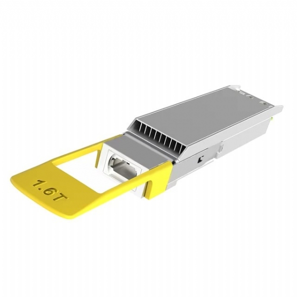
At 1.6T the air-cooled path is close to its limit. The OSFP MSA raised the OSFP1600 maximum module power to 42.9 W in Rev 5.22 (August 2025), up from 33 W, and OSFP-XD — a taller body, about 16.6 mm with an integrated heat sink against 10.5 mm for the riding-heat-sink version — is aimed at up to 40 W for future 1.6T ZR and 3.2T modules. The OSFP-XD lane guide covers what that volume does electrically; it does not repeal the fact that at some point moving air stops being enough.
That is where the flat top becomes the whole point rather than a compatibility nuisance. A liquid-cooled switch replaces the riding heatsink with a cold plate: the flat lid presses against a plate carrying coolant, and the fluid takes the heat out of the chassis. Platforms built on 100T-class switch silicon are designed this way, and their optics are ordered flat-top or RHS as a matter of course.
The thermal interface then becomes a real engineering variable: a conduction joint that is dry, contaminated or under-sprung has a much higher resistance than a designed one, and unlike a fin stack it gives no visual clue. This is one of the arguments that keeps co-packaged optics and XPO in the conversation, since both move the optical engine off the faceplate at the cost of field-replaceability. The comparison between those options is really a comparison of who owns the heat.
Before placing an 800G or 1.6T order, settle four things:
- Which cage: standard OSFP, OSFP-RHS or OSFP-XD, read off the switch hardware guide rather than the port speed.
- Whether the cage carries a riding heatsink. If it does you need flat-top; if it does not you need finned.
- Switch and host ends separately. One link often wants a finned module in the switch and a flat-top module in the NIC; ordering thirty-two of one is the classic error.
- Declared power class and airflow direction, against the per-port budget in the switch's documentation and against the rest of the rack.
We build finned, flat-top and OSFP-RHS variants of the same optical designs in Shenzhen, code them to your platform and software version, and treat the lid as an ordering option rather than a separate product family, so the optics do not change when the mechanics do. Every module is traffic-tested in the target platform and burned in at temperature before it ships, because a fault that only appears at 65 °C is not one you want the customer to find. Send us the switch model, the NIC model and the airflow direction and we will build the matching pair; the form-factor guide is the place to start if the cage type is not obvious.
FAQ
Can I take the fins off a finned module to make it flat-top? No. The finned lid is part of the module's thermal path and usually part of its EMI enclosure, and removing it voids every thermal and emissions claim on the datasheet. The flat-top variant is a different mechanical build, not a finned module with the top removed.
Will a flat-top module in a plain cage actually fail? Not necessarily, and that is the trap. At low power, in a cool hall, with good airflow and an empty neighbouring cage, it may run within limits indefinitely. At 16 W in a full faceplate it will not. The failure is load- and temperature-dependent, therefore intermittent, and far harder to diagnose than a refusal to seat.
What case temperature should I alarm on? The module's own declared high-warning threshold rather than a fixed number, because thresholds differ by module. More useful in practice is a relative alarm: any module more than about ten degrees above the median of its peers in the same chassis, whatever the absolute value.
Do passive DAC assemblies have this problem? No. Passive copper has no active components and no case temperature to monitor. In a thermally tight chassis, every in-rack link you can serve with copper removes watts from the faceplate instead of adding them.